


Bendix/King
KMA28
Audio Amplifier/Intercom/Marker Beacon Receiver
006-10565-0000 Page 2-11 Rev. 0, Sept. 2000
15. Verify that the audio selector panel system does not adversely affect any other aircraft
system by systematically switching the unit on and off, while monitoring the other
avionics and electrical equipment on the aircraft.
2.11.1.1 Marker Checkout
1. Connect a ramp generator at the antenna end of the marker coax. With the unit under
test in HI sensitivity, verify that a 160 µV, modulated 95% with 1300 Hz, signal will
illuminate the amber (M) marker light, and that marker audio is present in the head-
phones when the Marker Audio (MKR) push-button has been depressed. Select SPR
for speaker to verify marker audio availability on the cabin speaker. Verify that the
white (A) and blue (O) lights will illuminate within ± 3dB of the amber lamp, with
3000 HZ and 400 Hz applied, respectively.
2. Repeat with the unit in LOW sensitivity, with 430 µVolts applied.
3. Connect the marker antenna and verify proper operation.
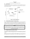
2.11.2 Receiver Sensitivity
Although the KMA28 meets FAA TSO-C35d sensitivity specifications, the sensitivity of
the receiver has been adjusted to meet real world requirements (150µV and 430µV, soft).
This will usually eliminate the need for the avionics shop to reduce the sensitivity in the
field so as to prevent early detection of the marker beacons. If your particular installation
requires more or less sensitivity, see adjustment section 2.6, and figure 2-1.
2.12 Cellular Interface Checkout
When a wireless telecommunication system is installed and configured, a dial tone will
appear in the headset of the pilot when the mic selector is in the “Tel” position. In “ALL”
intercom mode, a dial tone will be heard whenever the copilot or passenger’s hook switch
is closed.
2.13 Final Inspection
Verify that the wiring is bundled away from all controls and no part of the installation in-
terferes with aircraft control operation. Move all controls through their full range while
examining the installation to see that no mechanical interference exists. Verify that the
cables are secured to the aircraft structure in accordance with good practices, with ade-
quate strain relief. Ensure that there are no kinks or sharp bends in the cables and coaxial
cables. Verify that the cables are not exposed to any sharp edges or rough surfaces, and
that all contact points are protected from abrasion.
Complete log book entry, FAA Form 337, weight and balance computation and other
documentation as required. Sample text for FAA Form 337, and instructions for continu-
ing airworthiness can be found in Appendix D.
Return completed warranty registration application.