


Remote Control
49
CDR-882 User Manual Version 1.0 www.hhb.co.uk
Remote Control
In some installations, it may be desirable to control the CDR-882
from an external control system of some kind. Two rear panel
connectors are provided for this purpose, the Parallel Remote
Input and the RS232 Link Input. The Parallel Remote Input
provides the main transport commands only, while the RS232
Link Input allows control of virtually every machine function,
parameter and setting.
Parallel Remote Control Port
The rear panel Parallel Remote Input permits control of five
transport functions, and provides tallies for three functions. The
five active commands may be selected from a set of eight, and
the three active tallies from a set of five. These are shown in the
table below.
INPUTS
(COMMANDS)
Default
OUTPUTS
(TALLIES)
Default
PLAY/PAUSE Input 1 PLAY Output 7
RECORD Input 2 PAUSE Output 8
STOP Input 3 RECORD Output 9
AMS + Input 4 NO DISC -
AMS - Input 5 CHANGE OVER -
FFWD -
FRWD -
EJECT -
The commands and tallies listed in bold are the factory
defaults. If a different command set is preferred, an alternative
combination comprising any five (or less) of the eight available
commands, and any three (or less) of the five available tallies
may be reassigned to the inputs and outputs respectively via
the menu system. See page 36 for full details of changing the
default assignment.
The Parallel Remote Input is suitable for basic control of the
CDR-882 from a dedicated set of hardware switches or similar.
It is also possible to connect an external control system (e.g.
Crestron, AMX) to the Parallel Remote Input, using relays or
opto-coupled inputs and outputs within such systems.
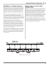
Pinout
The connector is a D9F. The pinout is shown in the table:
PIN FUNCTION
1
Input 1
2
Input 2
3
Input 3
4
Input 4
5
Input 5
6
0v
7
Output 1
8
Output 2
9
Output 3
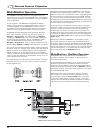
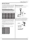
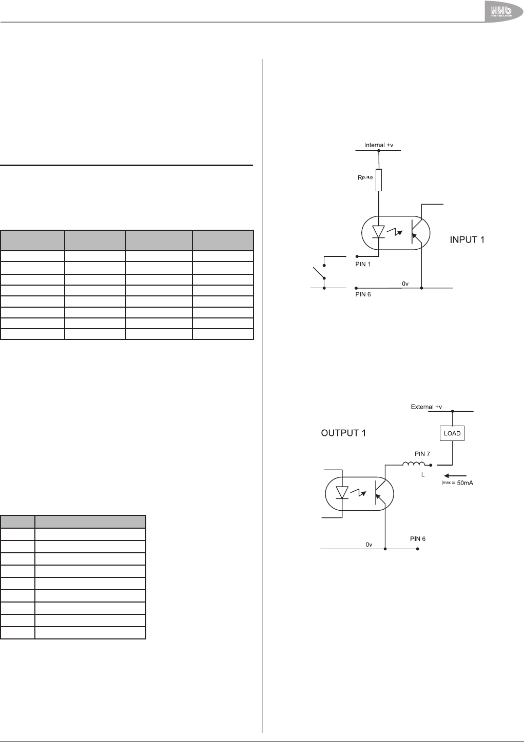
Electrical characteristics
Both inputs and outputs are internally opto-isolated, and include
a series inductor for EMC purposes.
The inputs simply require a short-to-ground for activation.
The outputs are open-collector, and go low when activated.
Loads such as LEDs may be connected externally with a suitable
series resistor, and returned to the +ve terminal of an external
PSU. The maximum current deliverable by the opto-isolator’s
transistor is 50mA. (The –ve side of the external voltage supply
should be referenced back to the CDR-882’s 0v on pin 6.)