


Basic Operation
23
CDR-882 User Manual Version 1.0 www.hhb.co.uk
Monitoring
The CDR-882 is equipped with a comprehensive audio
monitoring system, which includes the capability to monitor
playback from one drive while recording from an external
source on the other. (See page 18 for more information on
simultaneous record and playback.)
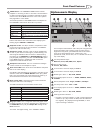
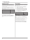
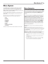
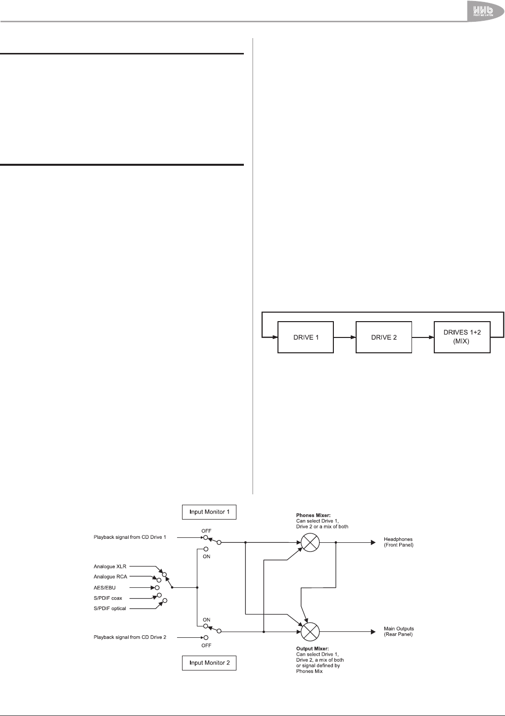
The diagram below is a simplified depiction of the CDR-882’s
monitoring system.
CDR-882 Monitoring system
The operation of the monitoring system depends on the status
of the two drives. The two input monitor switches in the
diagram above are “virtual” switches, not direct representations
of physical switches. Both are normally in “Off”, passing the
playback signal from the two drives to the Output and Phones
Mixers. Input Monitor 1 will switch “On” when Drive 1 is put in
RECORD, or if the front panel MONITOR function is selected.
Similarly, Input Monitor 2 will switch “On” when Drive 2 is put
in RECORD, or again, if the front panel MONITOR function is
selected.
In the diagram, Input Monitor 1 is shown “Off” and Input Monitor
2 “On”. This is the situation that would occur when Drive 1 is
playing and Drive 2 is simultaneously recording from an external
source. In this case, the two signals which are available to the
Phones and Output Mixers are the playback signal from Drive 1
and the currently-selected input signal. These two signals may
be selected individually by each Mixer, or a mix of both may be
selected.
Note that if a drive is in PLAY, it latches the Input Monitor for
that drive to OFF so that the playback audio is heard. Also, Input
Monitor cannot be re-enabled whilst the drive is in PLAY.
The MONITOR LED indicates the status of the Input Monitor
switches. If it is OFF, neither Input Monitor switches are active;
if it is ON, then the Input Monitor for the currently selected drive
(using DRIVE SELECT) is active; if it is flashing, then the Input
Monitor for the other drive (i.e., the drive NOT selected using
DRIVE SELECT) is active.
Main Outputs
The signal available at the CDR-882’s rear output connectors
may be the playback signal from, or the input signal to either
drive, or a mix of these.
The output is determined by settings in the Output Mix
submenu. Options are available here to audition either drive,
whether in playback or record, or to hear a mix of the signals
from both drives; see page 18 for full details. The default setting
is As Phones, wherein the output selection is determined by the
setting of the Phones Mix menu option (see below).
The CDR-882’s input signal (as selected by the I/P SELECT
button) may be routed to the outputs by pressing the MONITOR
button*. Note that this selection will also affect the headphones
output (see below).
Headphone Outputs
A front panel headphone socket is provided, whose monitoring
source may be selected independently of the main outputs. As
with the main outputs, the headphones may carry the playback
signal from either drive, the input signal, or a mix of these.
The playback signal heard at the headphones socket is primarily
determined by the PHONES SELECT button, which scrolls
through the three available options as follows:
The selected setting is indicated by the illumination of one or
both LEDs above the PHONES SELECT button. In the case of
the Mix option, what is heard in the headphones is determined
by the option selected in the Phones Mix submenu. See page 30
for full details of the options available.
The CDR-882’s input signal (as selected by the INPUT SEL
button) may be routed the to the headphone socket by pressing
the MONITOR button*. Note that this selection will also affect
the main output (see above).
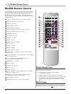
* Note that this function is also available from the RC-882
remote control, with the INPUT MONITOR button.
CDR-822 Monitoring System