


14
Setting the Interfaces
Using Smart Test
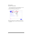
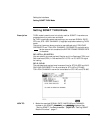
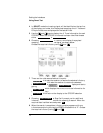
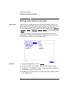
4 In SONET mode the incoming signal will be identified on the top line
of the display, and under this the payload mappings, the J1 Trace and
C2 byte indicators are displayed on the bottom lines.
5 Use the and keys to display the J1 Trace information for each
STS SPE. When the STS SPE of interest has been identified choose
either or .
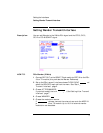
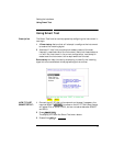
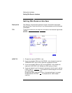
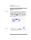
6 Choosing will identify and display the payload
mapping of the TUG structured signal, as shown below.
Choose the required tributary using and .
7 There are four choices available at this point:
which sets the receiver to receive the selected tributary.
which sets the receiver to receive the selected
tributary, exits to the display and starts
gating.
which displays the C2/V5/J1/J2 trace information for
the selected tributary.
which returns the display to the STS SPE selection
window.
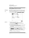
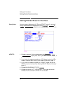
8 Choosing at Step 5 will prompt you for additional
information about patterns and which mapping to search. When the
required data has been entered press .
9 When the search is complete a tributary display appears, with any
tributaries containing the required PRBS indicated with a “P”. Choose
the required tributary using and .
VIEW PAYLOAD PRBS SEARCH
VIEW PAYLOAD
SETUP RX
TROUBLE SCAN
RESULTS
TROUBLE SCAN
VIEW LABELS
TOP LEVEL
PRBS SEARCH
GO