


94
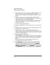
Making Measurements
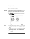
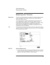
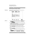
Measuring Jitter Transfer
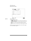
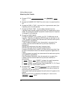
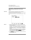
4 Choose JITTER on the
display.
5 Choose the NUMBER OF POINTS at which jitter is transmitted (3 to
55)
6 Choose the DWELL TIME - the time jitter is generated at each jitter
frequency point (5 to 30 seconds).
7 Choose the DELAY TIME - the time delay between the jitter
frequency/amplitude being applied and the error measurement being
made. This allows the network equipment to settle as jitter frequency
is changed (5 to 30 seconds).
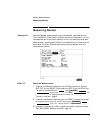
8 Choose the INPUT MASK.
If measuring SONET jitter transfer, the ITU-T G.958 mask can be
Type A or Type B and the Bellcore GR-253 mask can be High or Low.
TYPE A masks have good jitter tolerance and the mask corner points
are modified to compensate.
TYPE B masks have poorer jitter tolerance but a narrower jitter
transfer function and the mask corner points are modified to
compensate.
GR-253 Low mask covers the lower frequency band.
GR-253 High mask covers the upper frequency band.
If measuring 2 Mb/s jitter transfer,aQFactor choice is provided. Your
Q Factor choice should match the network equipment regenerator Q
Factor.
LOW Q systems have good jitter tolerance and the mask corner points
are modified to compensate.
High Q systems have poorer jitter tolerance but a narrower jitter
transfer function and the mask corner points are modified to
compensate.
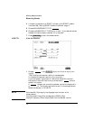
If (DSn) or (SONET) is chosen the mask frequencies
and amplitudes are displayed for information purposes.
If is chosen, choose the mask jitter frequencies, F1, F2, F3 and
F4, and mask jitter amplitudes A1 and A2.
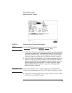
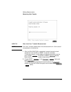
9 Choose MODE and press to start the calibration.
The Jitter Transfer display is replaced by an information display for
the duration of the Calibration.
A bar graph showing the progress of the calibration will appear on the
display.
When the Calibration is complete, the display will revert to the
display.
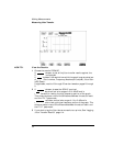
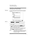
TRANSFER FUNCTION
TRANSMIT
JITTER
G.823 G.958
USER
CALIB
RUN/STOP
TRANSMIT
JITTER