


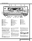
11 REAR PANEL CONNECTIONS
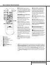
Rear Panel Connections
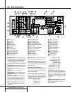
¤ Video Monitor Outputs: Connect this
jack to the composite or S-Video input of a TV
monitor or video projector to view the on-screen
menus and the output of any standard video
source selected by the receiver’s video switcher.
‹ DVD Video Inputs: Connect these jacks to
the composite or S-Video output jacks on a
DVD or other video source.
› Front Speaker Outputs: Connect these
outputs to the matching + or – terminals on
your left and right speakers.When making
speaker connections always make certain to
maintain correct polarity by connecting the red
(+) terminals on the AVR 520 to the red (+) ter-
minals on the speakers and the black (–) termi-
nals on the AVR 520 to the black (–) terminals
on the speakers. See page 16 for more informa-
tion on speaker polarity.
fi Center Speaker Outputs: Connect these
outputs to the matching + and – terminals on
your center channel speaker. In conformance
with the new CEA color code specification, the
Green Terminal is the positive, or "+" terminal
that should be connected to the red (+) termi-
nal on speakers with the older color coding.
Connect the black (–) terminal on the AVR to
the black negative (–) terminal on your speaker.
(See page 16 for more information on speaker
polarity.)
fl Surround Speaker Outputs: Connect
these outputs to the matching + and – termi-
nals on your surround channel speakers. In con-
formance with the new CEA color code specifi-
cation, the Blue terminal is the positive, or "+"
terminal that should be connected to the red
(+) terminal on the Surround Left speaker with
older color coding, while the Gray terminal
should be connected to the red (+) terminal on
the Surround Right speaker with the older color
coding. Connect the black (–) terminal on the
AVR to the matching black negative (–) termi-
nals for each surround speaker. (See page 17
for more information on speaker polarity.)
‡ Switched AC Accessory Outlet: This
outlet may be used to power any device you
wish to have turned on when the AVR 520 is
turned on with the
System Power Control
Button
2.
° Unswitched AC Accessory Outlet: This
outlet may be used to power any AC device.
The power will remain on at this outlet regard-
less of whether the AVR 520 is on or off.
NOTE: The total power consumption of all
devices connected to the accessory outlets
should not exceed 100 watts.
· AC Power Cord: Connect the AC plug to
an unswitched AC wall output.
a Video 2 Component Video Inputs:
Connect the Y/Pr/Pb component video outputs
of an HDTV Set-top convertor, satellite receiver,
or other video source device with component
video outputs to these jacks.
b Component Video Outputs: Connect
these outputs to the component video inputs of
a video projector or monitor.When a source
connected to one of the two
Component
Video Inputs
ac is selected the signal will
be sent to these jacks.
c DVD Component Video Inputs: Connect
the Y/Pr/Pb component video outputs of a DVD
player to these jacks.
d Remote IR Output: This connection per-
mits the IR sensor in the receiver to serve other
remote controlled devices. Connect this jack to
the “IR IN” jack on Harman Kardon (or other
compatible) equipment.
e Remote IR Input: If the AVR 520’s front-
panel IR sensor is blocked due to cabinet
doors or other obstructions, an external IR
sensor may be used. Connect the output of
the sensor to this jack.
f Multiroom IR Input: Connect the output of
an IR sensor in a remote room to this jack to
operate the AVR 520’s multiroom control system.
g Video 1 Video Outputs: Connect these
jacks to the
RECORD/INPUT composite or
S-Video jack on a VCR.
h Video 1 Video Inputs: Connect these
jacks to the
PLAY/OUT composite or S-Video
jacks on a VCR or other video source.
i Video 2 Video Outputs: Connect these
jacks to the
RECORD/INPUT composite or
S-Video jacks on a VCR.
j Video 3 Video Inputs: Connect these
jacks to the
PLAY/OUT composite or S-Video
jacks on a VCR or other video source.
k Video 2 Video Inputs: Connect these
jacks to the
PLAY/OUT composite or S-Video
jacks on a VCR or other video source.
Optical Digital Inputs: Connect the opti-
cal digital output from a DVD player, HDTV
receiver, the S/P-DIF output of a compatible
computer sound card playing MP3 files or
streams, LD player or CD player to these jacks.
The signal may be either a Dolby Digital signal,
a DTS signal or a standard PCM digital source.
Coaxial Digital Inputs: Connect the coax
digital output from a DVD player, HDTV receiver,
the S/P-DIF output of a compatible computer
sound card playing MP3 files or streams, LD player
or CD player to these jacks. The signal may be
either a Dolby Digital signal, DTS signal or a stan-
dard PCM digital source. Do not connect the RF
digital output of an LD player to these jacks.
Video 2 Audio Outputs: Connect these
jacks to the
RECORD/INPUT audio jacks on a
VCR or other video source.
Video 2 Audio Inputs: Connect these
jacks to the
PLAY/OUT audio jacks on a VCR
or other video source.
Video 3 Audio Inputs: Connect these
jacks to the
PLAY/OUT audio jacks on a VCR
or other video source.
Video 1 Audio Inputs: Connect these
jacks to the
PLAY/OUT audio jacks on a VCR
or other video source.
Video 1 Audio Outputs: Connect these
jacks to the
RECORD/INPUT audio jacks on a
VCR.
Preamp Outputs: When the jumper pins
that link the
Amplifier Inputs with these
outputs are removed, these jacks may be con-
nected to an external power amplifier.
Amplifier Inputs: When the jumper pins
that link the
Preamp Outputs with these
inputs are removed, these jacks may be used to
connect an external source or the AVR 520’s
multiroom system to the internal amplifiers.
38
39
39
38
37
36
35
34
33
32
31