


17 INSTALLATION AND CONNECTIONS
Installation and Connections
television set or any other video source to the
Video 3 j jacks.
3. Connect the analog audio and video out-
puts of a DVD or laser disc player to the
DVD
jacks §‹.
4. Connect the digital audio outputs of a DVD
player, satellite receiver, cable box or HDTV con-
verter to the appropriate
Optical or Coaxial
Digital Inputs
*Ó.
5. Connect the
Video Monitor Output ¤
jacks on the receiver to the composite or S-
Video input of your television monitor or video
projector.
6. If your DVD player and monitor both have
component video connections, connect the
component outputs of the DVD player to the
DVD Component Video Inputs c. Note
that even when component video connections
are used, the audio connections should still be
made to either the analog
DVD Audio Inputs
§ or any of the Optical or Coaxial Digital
Input Jacks
.
7. If another component video device is avail-
able, connect it to the
Video 2 Component
Video Input Jacks
a. The audio connections
for this device should be made to either the
Video 2 Audio Input Jacks or any of the
Optical or Coaxial Digital Input Jacks
.
8. If the component video inputs are used, con-
nect the
Component Video Output b to
the component video inputs of your TV, projec-
tor or display device.
9. If you have a camcorder, video game or other
audio/video device that is connected to the AVR
on a temporary, rather than permanent basis,
connect the audio, video and digital audio out-
puts of that device the
Front Panel Inputs
*ÓÔ. A device connected here is selected
as the Video 4 input, and the digital inputs
must be assigned to the Video 4 input. (See
page 20 for more information on input configu-
ration.)
Video Connection Notes:
• When the component video jacks are used,
the on-screen menus are not visible and you
must switch to the standard composite or S-
Video input on your TV to view them.
• The AVR 520 will accept either standard
composite, S-Video or Y/Pr/Pb component
video signals. However, it will not convert
composite or S signals to component video.
• Component or composite video signals may
only be viewed in their native formats.
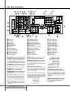
System and Power Connections
The AVR 520 is designed for flexible use with
multiroom systems, external control compo-
nents and power amplifiers.
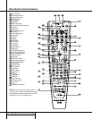
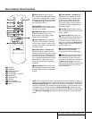
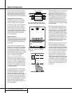
Main Room Remote Control Extension
If the receiver is placed behind a solid or
smoked glass cabinet door, the obstruction may
prevent the remote sensor from receiving com-
mands. In this event, an optional remote sensor
may be used. Connect the output of the remote
sensor to the
Remote IR Input jack e.
If other components are also prevented from
receiving remote commands, only one sensor is
needed. Simply use this unit’s sensor or a
remote eye by running a connection from the
Remote IR Output jack d to the Remote IR
Input jack on Harman Kardon or other compati-
ble equipment.
Multiroom IR Link
The remote room IR receiver should be connected
to the AVR 520 via standard coaxial cable. Plug
the IR connection cable into the
Multiroom IR
Input
jack f on the AVR 520’s rear panel.
If other Harman Kardon compatible source
equipment is part of the main room installation,
the
Remote IR Output jack d on the rear
panel should be connected to the IR IN jack on
source equipment. This will enable the remote
room location to control source equipment func-
tions.
NOTE: All remotely controlled components
must be linked together in a “daisy chain”.
Connect the
IR OUT jack of one unit to the IR
IN
of the next to establish this chain.
Multiroom Audio Connections
Depending on the distance from the AVR 520
to the remote room, two options are available
for audio connection:
Option 1: Use high-quality, shielded audio
interconnect cable from the AVR 520’s location
to the remote room. In the remote room, con-
nect the interconnect cable to a stereo power
amplifier.The amplifier will be connected to the
room’s speakers. At the AVR 520, plug the
audio interconnect cables into the
Multiroom
Output Jacks
• on the AVR 520’s rear panel.
Option 2: Connect the Multiroom Output
Jacks
• on the AVR 520 to the inputs of an
optional stereo power amplifier. Run high-quali-
ty speaker wire from the amplifier to the speak-
ers in the remote room.
NOTE: In both options, you may connect an
optional IR sensor in the remote room to the
AVR 520 via an appropriate cable. Connect the
sensor’s cable to the
Multiroom IR Input f
on the AVR 520 and use the Zone II remote to
control the room volume. Alternatively, you may
install an optional volume control between the
output of the amplifiers and the speakers.
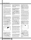
AC Power Connections
This unit is equipped with two accessory AC
outlets. They may be used to power accessory
devices, but they should not be used with high-
current draw equipment such as power ampli-
fiers. The total power draw to each outlet may
not exceed 100 watts.
The
Switched AC Accessory Outlet ‡ will
receive power only when the unit is on. This is
recommended for devices that have no power
switch or a mechanical power switch that may
be left in the “ON” position.
NOTE: Many audio and video products go into
a Standby mode when they are used with
switched outlets, and cannot be fully turned on
using the outlet alone without a remote control
command.
The
Unswitched AC Accessory Outlet °
will receive power as long as the unit is
plugged into a powered AC outlet.
Finally, when all connections are complete, plug
the power cord into a nonswitched 110-volt AC
wall outlet.You’re almost ready to enjoy the
AVR 520!
32
31
34
32
31
32
31
35