


rect button while entering a direct frequency,
press the
Clear Button to start over.
NOTE: When the FM reception of a station is
weak, audio quality will be increased by switch-
ing to Mono mode by pressing the
FM Mode
Button
^
s
until the STEREO indicator
V goes out.
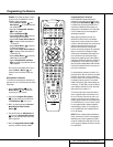
Preset Tuning
Using the remote, up to 30 stations may be
stored in the AVR 520’s memory for easy recall
using the front panel controls or the remote.
To enter a station into the memory, first tune
the station using the steps outlined above.
Then:
1. Press the
Memory Button on the
remote. Note that the
MEMORY Indicator
U will be illuminated and flash in the Main
Information Display
˜.
2. Within five seconds, press the
Numeric
Keys
r corresponding to the location where
you wish to store this station’s frequency. Once
entered, the preset number will appear in the
Preset Number/Sleep Timer display R.
3. Repeat the process after tuning any addition-
al stations to be preset.
Recalling Preset Stations
• To manually select a station previously
entered in the preset memory, press the
Numeric Keys r that correspond to the
desired station’s memory location.
• To manually tune through the list of stored
preset stations one by one, press the
Preset
Stations Selector Buttons
#
©
on
the front panel or remote.
Tape Recording
In normal operation, the audio or video source
selected for listening through the AVR 520 is
sent to the record outputs. This means that any
program you are watching or listening to may
be recorded simply by placing machines con-
nected to the outputs for
Tape Outputs ¢ or
Video 1 or 2 Outputs gi in the
record mode.
When a digital audio recorder is connected to
the
Digital Audio Outputs , you are able
to record the digital signal using a CD-R,
MiniDisc or other digital recording system.
Front Panel Connections
In addition to the rear panel digital outputs, the
AVR 520 offers Harman Kardon’s exclusive con-
figurable front panel output jack feature. For
easy connection of portable devices, you may
switch the front panel
Digital Coax Jack Ó
or the Video 4 Jacks Ô from an input to an
output by following these steps:
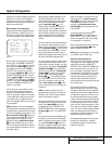
1.Press the
OSD Button v to view the
MASTER MENU (Figure 1).
2.Press the
Set Button p to enter the
IN/OUT SETUP menu (Figure 2).
3.Press the
¤
Button n so that the on-
screen
›
cursor is next to VIDEO 4 or
COAXIAL 3 depending on which input
you wish to change to an output. Either
input, or both may be changed at any time.
4.Press the
Set Button p and then press
either of the
‹
/
›
Buttons o/ so that
the word
IN is highlighted.
5.Press the
Set Button p to enter the
change.
6.Press the
OSD Button v to exit the
menus and return to normal operation.
Note that once the setting is made, the appro-
priate
Input/Output Status Indicator (
will turn red, indicating that the selected ana-
log or digital jacks are now an output, instead
of in the default setting as an input. Once
changed to an output, the setting will remain
as long as the AVR 520 is turned on, unless the
setting is changed in the OSD menu system, as
described above. Note, however, that once the
AVR 520 is turned off, the setting is cancelled.
When the unit is turned on again, the front
panel jacks will return to their normal default
setting as an input. If you wish to use their
jacks as an output at a future time, the setting
must be changed again using the OSD menu
system, as described above.
NOTES:
• The digital outputs are active only when a
digital signal is present, and they do not con-
vert an analog input to a digital signal, or
change the format of the digital signal. In
addition, the digital recorder must be com-
patible with the output signal. For example,
the PCM digital input from a CD player may
be recorded on a CD-R or MiniDisc, but Dolby
Digital or DTS signals may not.
• Please make certain that you are aware of
any copyright restrictions on any material you
copy. Unauthorized duplication of copyrighted
materials is prohibited by federal law.
Output Level Trim Adjustment
Normal output level adjustment for the AVR
520 is established using the test tone, as out-
lined on pages 23 and 24. In some cases, how-
ever, it may be desirable to adjust the output
levels using program material such as a test
disc, or a selection you are familiar with.
Additionally, the output level for the subwoofer
can only be adjusted using this procedure.
To adjust the output levels using program
material, first set the reference volume for the
front left and front right channels using the
Volume Control ı
î
.
If you are using a disc with test signals or an
external signal generator as the source from
which to trim the output levels, you may use
the EzSet feature of the remote to guide you to
the correct SPL level. To use the remote for this
purpose, press and quickly release the
SPL
Indicator Select
to activate the sensor.
While the test tone is circulating, the
Program/SPL Indicator c will change color
to indicate the level. Adjust the level as shown
above until the LED lights green for all chan-
nels. When it is red the level is too high; when
it is amber the level is too low. Press the
SPL
Indicator Select
to turn the sensor and
indicator off.
Once the reference level has been set, press
the
Channel Select button
m
Ù and note
that
FRONT L LEV will appear in the
Main Information Display Y. To change
the level, first press the
Set Button p@,
and then use the
Selector Buttons 7$ or
the
⁄
/
¤
Buttons
n
to raise or lower the
level. DO NOT use the volume control, as this
will alter the reference setting.
Once the change has been made, press the
Set
Button
p@ and then press the Selector
Buttons
7$ or the
⁄
/
¤
buttons
n
to
select the next output channel location that you
wish to adjust. To adjust the subwoofer level,
press the
Selector Buttons 7$ or the
⁄
/
¤
Buttons
n
until WOOFER LEV
appears in the Main Information Display Y
or on-screen display.
Press the
Set Button p@ when the name
of the desired channel appears in the
Main
41
41
40
37
35
37
33
33
35
34
32 OPERATION
Operation