


5 FRONT PANEL CONTROLS
1 Main Power Switch: Press this button to
apply power to the AVR 520. When the switch
is pressed in, the unit is placed in a Standby
mode, as indicated by the amber
Power
Indicator
3 surrounding the System
Power Control
2. This button MUST be
pressed in to operate the unit. To turn the unit
off and prevent the use of the remote control,
this switch should be pressed until it pops out
from the front panel so that the word “OFF”
may be read at the top of the switch.
NOTE: This switch is normally left in the “ON”
position.
2 System Power Control: When the Main
Power Switch
1
is “ON,” press this button
to turn on the AVR 520; press it again to turn
the unit off. Note that the
Power Indicator
3
surrounding the switch will turn green
when the unit is on.
3 Power Indicator: This LED will be lit in
amber when the unit is in the Standby mode to
signal that the unit is ready to be turned on.
When the unit is in operation, the indicator will
turn green.
4 Headphone Jack: This jack may be used to
listen to the AVR 520’s output through a pair of
headphones. Be certain that the headphones
have a standard
1
/4" stereo phone plug. Note
that the main room speakers will automatically
be turned off when the headphone jack is
in use.
5 Dolby Mode Selector: Pressing this selec-
tor button cycles the AVR through the various
Dolby surround modes. The first press of the but-
ton switches the surround mode to the last
Dolby surround mode that was in use. Each sub-
sequent press selects the next mode in the fol-
lowing order:
6 DTS Surround Mode Selector: Pressing
this selector button cycles the AVR through the
DTS surround modes. The first press of the but-
ton selects the last DTS surround mode that
DOLBY 3 STEREO
DOLBY
DIGITAL
DOLBY PRO LOGIC II MUSIC
DOLBY PRO LOGIC II
MOVIES
DOLBY PRO LOGIC II
EMULATION
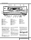
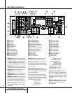
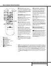
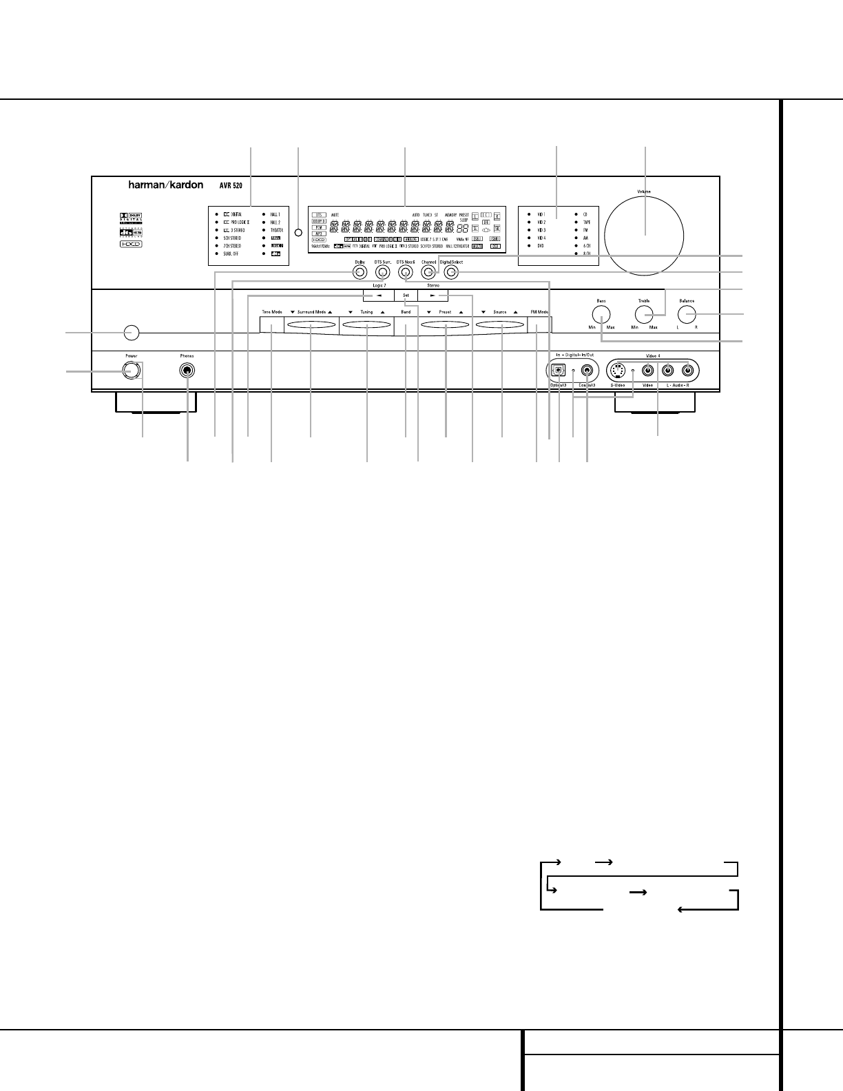
Front Panel Controls
1 Main Power Switch
2 System Power Control
3 Power Indicator
4 Headphone Jack
5 Dolby Mode Selector
6 DTS Surround Mode Selector
7 Logic 7 Mode Selector /‹ Button
8 Tone Mode
9 Surround Mode Selector
) Tuning Selector
! Tuner Band Selector
@ Set Button
# Preset Station Selector
$ Stereo Mode Selector /› Button
% Input Source Selector
^ FM Mode Selector
& DTS Neo:6 Mode Selector
* Digital Optical 3 Input
( Input/Output Status Indicator
Ó Digital Coax 3 Jack
Ô Video 4 Input Jacks
Bass Control
Ò Balance Control
Ú Treble Control
Û Digital Select Button
Ù Channel Select Button
ı Volume Control
ˆ Input Indicators
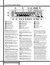
˜ Main Information Display
¯ Remote Sensor Window
˘ Surround Mode Indicators
2
4
79
@
˘
Ú
ı
¯
Û
Ù
1
3
5
6
8
)
!
#
$
%
^
&
Ó
*
(
Ô
Ò
ˆ
˜