


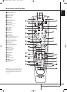
8 REAR PANEL CONNECTIONS
Rear Panel Connections
9
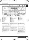
6-Channel Direct Inputs: These jacks are
used for connection to source devices such as
DVD-Audio or SACD players with discrete analog
outputs.
A
Digital Audio Outputs: Connect these
jacks to the matching digital input connector on
a digital recorder such as a CD-R or MiniDisc
recorder.
B
Video Monitor Outputs: Connect this jack
to the composite and/or S-Video input of a TV
monitor or video projector to view the on-screen
menus and the output of any standard Video or
S-Video source selected by the receiver’s video
switcher.
C
DVD Video Inputs: Connect these jacks to
the composite or S-Video output jacks on a DVD
player or other video source.
D
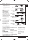
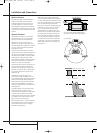
Front Speaker Outputs: Connect these
outputs to the matching + or – terminals on
your left and right speakers. In conformance with
the new CEA color code specification, the White
terminal is the positive, or "+" terminal that
should be connected to the red (+) terminal on
Front Left speaker with the older color coding,
while the Red terminal is the positive, or "+"
terminal that should be connected to the red (+)
terminal on Front Right speaker. Connect the
black (–) terminals on the AVR to the black (–)
terminals on the speakers. See page 13 for more
information on speaker polarity.
E
Center Speaker Outputs: Connect these
outputs to the matching + and – terminals on
your center channel speaker. In conformance
with the new CEA color code specification, the
Green Terminal is the positive, or "+" terminal
that should be connected to the red (+) terminal
on speakers with the older color coding. Connect
the black (–) terminal on the AVR to the black
negative (–) terminal on your speaker. (See page
13 for more information on speaker polarity.)
F
Surround Speaker Outputs: Connect
these outputs to the matching + and – terminals
on your surround channel speakers. In confor-
mance with the new CEA color code specifica-
tion, the Blue terminal is the positive, or "+"
terminal that should be connected to the red (+)
terminal on the Surround Left speaker with older
color coding, while the Gray terminal should be
connected to the red (+) terminal on the
Surround Right speaker with the older color
coding. Connect the black (–) terminal on the
AVR to the matching black negative (–)
terminals for each surround speaker. (See page
13 for more information on speaker polarity.)
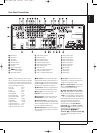
G
Switched AC Accessory Outlet:This
outlet may be used to power any device that you
wish to have turn on when the AVR is turned on
with the System Power Control switch
2
.
Note: The total power consumption of all
devices connected to the accessory outlets
should not exceed 50 W from the Switched
Outlet
G
.
H
Video 1 Audio Inputs: Connect these jacks
to the PLAY/OUT audio jacks on a TV or other
audio or video source.
I
AC Power Cord: Connect the AC plug to an
unswitched AC wall output.
J
Video 2 Component Video Inputs:
Connect the Y/Pr/Pb component video outputs of
an HDTV Set-top convertor, satellite receiver, or
other video source device with component video
outputs to these jacks.
K
Monitor Component Video Outputs:
Connect these outputs to the component video
inputs of a video projector or monitor.When a
source connected to one of the two
Component Video Inputs
JL
is selected
the signal will be sent to these jacks.
L
Video 1 Component Video Inputs:
Connect the Y/Pr/Pb component video outputs of
a DVD player to these jacks.
Note: All component inputs/outputs can be
used for RGB signals too, in the same way as
described for the Y/Pr/Pb signals, then connected
to the jacks with the corresponding color.
RGB connection is not possible if the source out-
puts a separate sync signal (see page 15).
M
Video 2 Audio Inputs: Connect these jacks
to the PLAY/OUT audio jacks on a second VCR
or other audio or video source.
N
Coaxial Digital Inputs: Connect the coax
digital output from a DVD player, HDTV receiver,
the output of a compatible computer sound card
playing MP3 files or streams, LD player, MD
player or CD player to these jacks. The signal
may be either a Dolby Digital signal, DTS signal,
a 2 channel MPEG 1 signal, or a standard PCM
digital source. Do not connect the RF digital out-
put of an LD player to these jacks.
O
Video 2 Video Inputs: Connect these jacks
to the PLAY/OUT composite or S-Video jacks on
a second VCR or other video source.
P
Video 1 Video Outputs: Connect these
jacks to the RECORD/INPUT composite or
S-Video jack on a VCR.
Q
Video 1 Video Inputs: Connect these jacks
to the PLAY/OUT composite or S-Video jacks on
a TV or other video source.
R
Optical Digital Inputs: Connect the
optical digital output from a DVD player, HDTV
receiver, the output of a compatible computer
sound card playing MP3 files or streams, LD
player, MD player or CD player to these jacks.
The signal may be either a Dolby Digital signal, a
DTS signal, a 2 channel MPEG 1 signal, or a
standard PCM digital source.
S
RS-232 Serial Port: This specialized
connector may be used with your personal
computer in case Harman Kardon offers a
software upgrade for the receiver at some time
in the future.
T
RS-232 Mode: Leave this switch popped
out in the Operate position unless the AVR 147
is being upgraded.
U
RS-232 Reset: This switch is only used
during a software upgrade.A standard processor
reset is performed by pressing and holding the
front-panel Tone button.
V
HDMI Inputs: Connect the HDMI output of
video sources such as a DVD player, set-top box
or HDTV tuner to either of these jacks.
W
HDMI Output: Connect this jack to the
HDMI input on a compatible HDMI-equipped
video display.
NOTE ON VIDEO CONNECTIONS: When
connecting a video source product such as a
VCR, DVD player, satellite receiver, cable set-top
box, personal video recorder or video game to
the AVR 147, you may use either a composite or
S-video connection, but not both.
33639_AVR147_ENG 10/07/07 13:45 Side 8