Reference Manual
00809-0100-4696, Rev AA
September 2004
C-13
Rosemount 848L
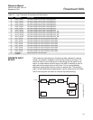
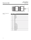
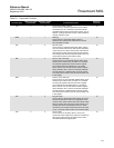
Table C-6. Parameters and
Description
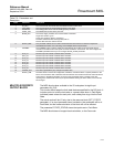
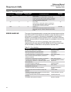
MULTIPLE DISCRETE
OUTPUT BLOCK
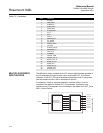
The MDO block makes available to the I/O subsystem its eight input
parameters IN_D1/8.
This function block keeps the fault state features specified for the DO block. It
includes option to hold the last value or a preset value when in Fault State,
individual preset values for each point, and a delay time to go into the Fault
State.
The actual mode will be LO only due to the resource block (SET_FSTATE
parameter). If an input parameter has a bad status, that parameter will be in
Fault State, but the mode calculation of the block will not be affected.
The parameter FSTATE_STATUS shows that points are in Fault State.
The MDO block does not support back calculation, or the Cas mode.
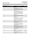
Index Parameter Description
1 ST_REV The revision level of the static data associated with the function block.
2 TAG_DESC The user description of the intended application of the block.
3 STRATEGY The strategy field can be used to identify grouping of blocks.
4 ALERT_KEY The identification number of the plant unit.
5 MODE_BLK The actual, target, permitted, and normal modes of the block:
Target: The mode to .go to.
Actual: The mode the .block is currently in.
Permitted: Allowed modes that target may take on
Normal: Most common mode for actual
6 BLOCK_ERR This parameter reflects the error status associated with the hardware or software components
associated with a block. It is a bit string, so that multiple errors may be shown.
7 CHANNEL The CHANNEL value is used to select the measurement value. Refer to the appropriate device
manual for information about the specific channels available in each device. You must configure the
CHANNEL parameter before you can configure the XD_SCALE parameter.
8 OUT_D1 Discrete output to indicate a selected alarm condition.
9 OUT_D2 Discrete output to indicate a selected alarm condition.
10 OUT_D3 Discrete output to indicate a selected alarm condition.
11 OUT_D4 Discrete output to indicate a selected alarm condition.
12 OUT_D5 Discrete output to indicate a selected alarm condition.
13 OUT_D6 Discrete output to indicate a selected alarm condition.
14 OUT_D7 Discrete output to indicate a selected alarm condition.
15 OUT_D8 Discrete output to indicate a selected alarm condition.
16 UPDATE_EVT This alert is generated by any change to the static data.
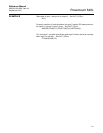
17 BLOCK_ALM The block alarm is used for all configuration, hardware, connection failure or system problems in the
block. The cause of the alert is entered in the subcode field. The first alert to become active will set the
Active status in the Status parameter. As soon as the Unreported status is cleared by the alert
reporting task, another block alert may be reported without clearing the Active status, if the subcode
has changed.


