Reference Manual
00809-0100-4696, Rev AA
September 2004
2-9
Rosemount 848L
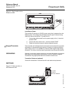
TRANSMITTER LABEL
Figure 2-7. Transmitter Label
INSTALLATION
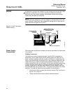
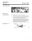
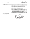
Using Cable Glands Use the following steps to install the 848L with Cable Glands:
1. Remove the junction box cover by unscrewing the four cover screws.
2. Run the sensor and power/signal wires through the appropriate cable
glands using the pre-installed cable glands (see Figure 2-8).
3. Install the I/O wires into the correct screw terminals.
4. Install the power/signal wires onto the correct screw terminals. Bus
power is polarity insensitive, allowing the user to connect positive (+)
or negative (–) to either Fieldbus wiring terminal labeled “Bus.” I/O
power is polarity sensitive and must be connected correctly to avoid
damage to the transmitter. See Figure 2-4 on page 2-5.
5. Replace the enclosure cover and securely tighten all cover screws.
Figure 2-8. Installing the 848L
with Cable Glands
848/848_21_AA.EPS
Cable Gland
Power/Signal
I /O
848_848A19A
Enclosure Cover
Screw (4)


