


Reference Manual
00809-0100-4696, Rev AA
September 2004
Rosemount 848L
2-4
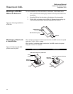
WIRING If the device or sensors are installed in a high-voltage environment and a fault
condition or installation error occurs, the sensor leads and transmitter
terminals could carry lethal voltages. Use extreme caution when making
contact with the leads and terminals.
NOTE
Do not apply high voltage (e.g. AC line voltage) to the transmitter bus or I/O
power terminals. Abnormally high voltage can damage the unit (bus and I/O
power terminals are rated to 42.4 VDC).
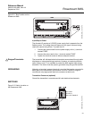
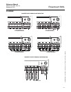
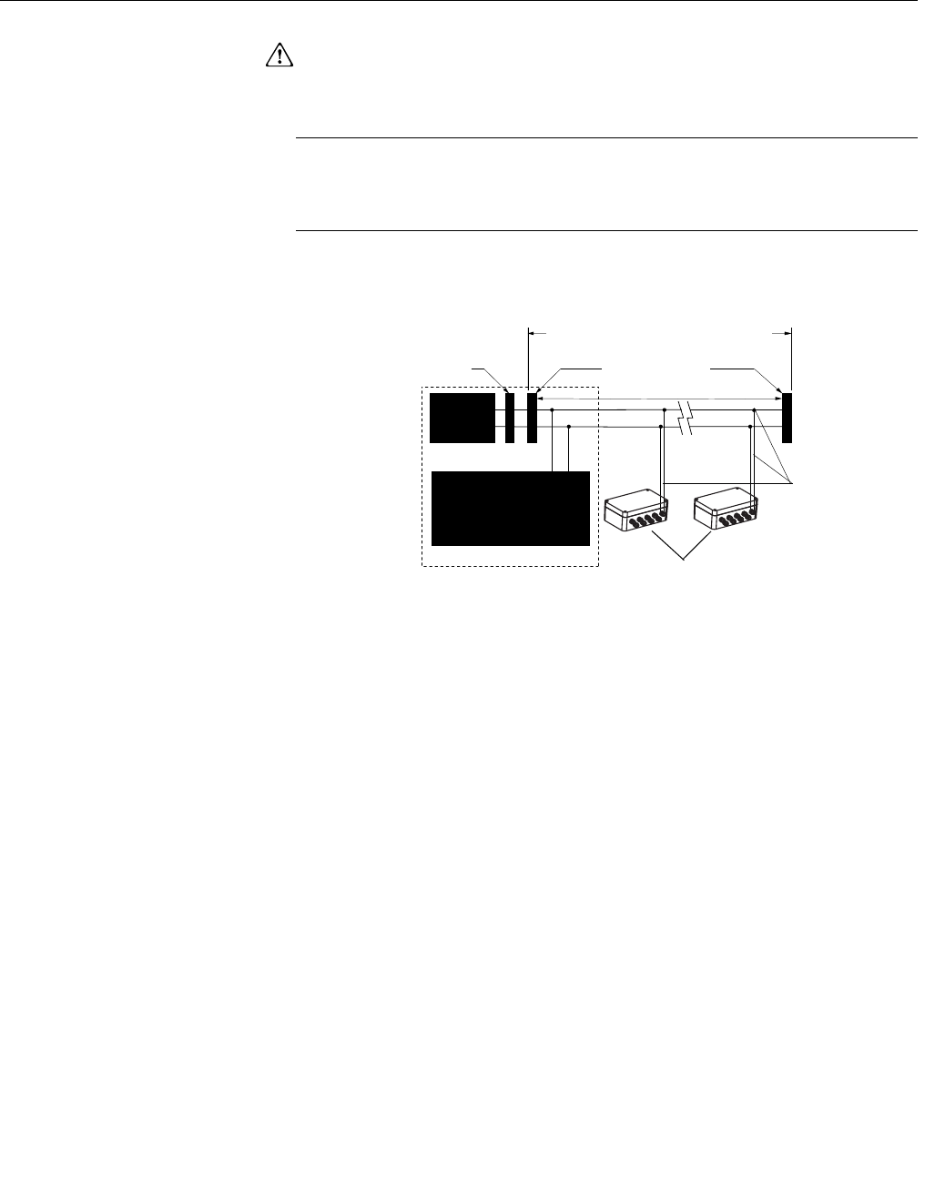
Figure 2-3. 848L Transmitter
Fieldbus Wiring
Power Supply
Connections
The transmitter requires both a fieldbus connection and power for the discrete
I/O channels.
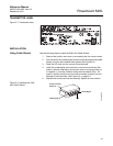
Fieldbus Connection
The fieldbus connection requires between 9 and 32VDC to operate the
electronics. The dc power supply should provide power with less than 2%
ripple. A fieldbus segment requires a power conditioner to isolate the power
supply filter and decouple the segment from other segments attached to the
same power supply. Signal wiring should be shielded, twisted pair for best
results in electrically noisy environments. Do not use unshielded signal wiring
in open trays with power wiring or near heavy electrical equipment. Use
ordinary copper wire of sufficient size to ensure that the voltage across the
bus terminals does not go below 9 VDC. The power terminals are not polarity
sensitive. To power the electronics and establish communications:
1. Connect the fieldbus wires to the terminals marked "Bus" as shown in
Figure 2-4 on page 2-5.
2. Tighten the terminal screws to ensure adequate contact.
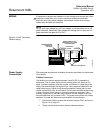
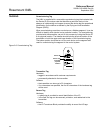
Power
Supply
Terminators
Devices 1 through 16*
Integrated Power
Conditioner
and Filter
(Spur)
(Spur)
Signal
Wiring
FOUNDATION
fieldbus Host or
configuration tool
6234 ft (1900 m) max
(depending upon cable
characteristics)
848-848_01A
(Trunk)