


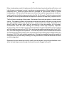


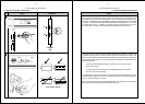
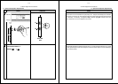


A-Chain Alignment Procedures
Step
No.
4-14
IndicationAction
✓
x
x
Out of phase
Incorrect azimuth
..
..
00
00
55
55
..
..
11
11
..
..
22
22
..
..
44
44
..
..
88
88
11
11
..
..
66
66
33
33
..
..
11
11
55
55
66
66
..
..
33
33
11
11
22
22
..
..
55
55
kk
kk
HH
HH
zz
zz
dd
dd
BB
BB
––
––
11
11
00
00
++
++
55
55
00
00
––
––
55
55
++
++
11
11
00
00
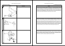
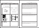
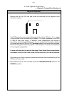
OUT OF
FOCUS
INTO
FOCUS
X
✓
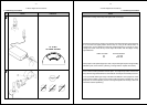
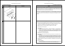
b. Optical Preamplifier Adjustments
1
12
1
13
OSCILLOSCOPE TRACES
RTA DISPLAY
Cat. No. 240A
X
Y
Proj. 1 Status
RV101 Gain
RV102 hf
RV201 Gain
RV202 hf
TP501 L tp
TP502 R tp
R
L
RV301 Gain
RV302 hf
RV401 Gain
RV402 hf
Proj. 2 Status
TP503 GND
R
R
L
L
SIGNAL
PRESENT
RT
SCOPE
X-Y
MODE
IN
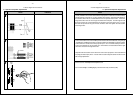
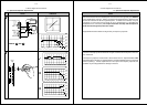
A-Chain Alignment Procedures
Notes
4-15
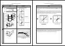
b. Optical Preamplifier Adjustments
Remove the Cat. No. 97 film and thread and play the pink noise on the Cat. No. 69 film
(emulsion away from screen). Connect the RTA to the left test point TP501 L on the Cat.
No. 240A.
Switch the oscilloscope to the X/Y mode and adjust the azimuth of the projector optics for
the narrowest diagonal trace. (Blooming at the ends of the trace may be caused by
improper lighting of the edges of the optical tracks. If necessary, repeat steps 8 and 9
above, or step 5 on page 4-4 to reduce such blooming to a minimum.)
Then, while observing the trace on the RTA, adjust the focus of the sound track lens for
the best high frequency response. The trace shown in the example is ideal; merely
attempt to obtain the best response. The azimuth and focus adjustments interact so you
must repeat Steps 12 and 13 until no further adjustments are required.
x x
Not enough light
on one channel
Uneven light on cell