


A-Chain Alignment Procedures
Step
No.
4-10
IndicationAction
b. Optical Preamplifier Adjustments
L
L
L
L
RR
RR
✓
✓
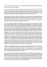
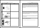
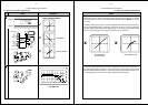
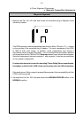
OSCILLOSCOPE TRACES
Rt
Lt
CAT NO.
222
7
8
Dolby
Rt
Lt
Lt
Rt
gnd
Proj. 2
hf
GAIN
hf
GAIN
Rt tp
Rt
Lt
Lt tp
Proj. 1
hf
GAIN
hf
GAIN
signal
present
Cat. No.
240A
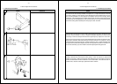
A-Chain Alignment Procedures
Notes
4-11
b. Optical Preamplifier Adjustments
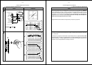
Thread and play the Dolby tone side of the Cat. No. 69 test film for an initial test of the
signal path through the projector preamplifier. The film emulsion should face away from
the screen. Adjust the Cat. No. 240A Proj 1 L and R gain potentiometers until the LEDs
on the Cat. No. 222 Dual Noise Reduction Module indicate the Dolby level — the center
two green LEDs are lit. In addition, verify that the signal present LEDs on the Cat.
No. 240A are lit. The Dolby tone signal should be visible on the oscilloscope.
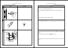
Remove the Cat. No. 69 test film and thread the SMPTE Buzz Track Film. This film has
modulation just beyond the normally scanned areas of the optical sound tracks. The
objective of this test is to ensure that the slit illuminates only the sound-tracks. Depending
on the design of the projector, the positioning of the slit relative to the optical tracks is
adjusted as follows:
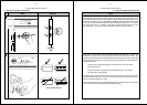
The film guide is adjusted laterally for a null if the lens and exciter lamp
are fixed in position;
The lens and exciter lamp assembly are adjusted laterally for a null if the
film cannot be moved laterally.
The adjustment is correct when there is no signal output while the film is played. It may
not be possible to adjust for a null with some older slits; in such instances, adjust for a
minimum and equal signal on L and R.
Some projectors use a lens with an adjustable slit width. The adjustment is correct at the
point when the left and right signals both disappear equally.