


2-2
Locate the power amplifiers away from the Cat. No. 240A optical preamplifier
to avoid hum pickup problems.
STEP 4 Disconnect power from the existing cinema sound equipment.
STEP 5 Disconnect all cabling from the existing cinema sound processing system,
but do not disconnect the wiring from power amplifiers, etc.
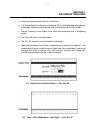
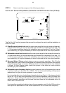
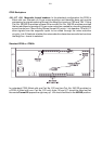
STEP 6 Check that the CP65 voltage selector switch is set correctly for your mains
voltage and that the correct fuses are installed. (The selector switch is
located on the rear of the Cat. No. 259 Power Supply and can be seen
through the backplane.)
DISCONNECT THE CP65 FROM POWER BEFORE YOU TURN THE
SELECTOR SWITCH FROM ONE POSITION TO ANOTHER.
The CP65 accepts both 50 Hz and 60 Hz power. The mains voltages must
fall within the following limits:
Voltage Acceptable
Setting Voltage Range Fuse Type
100 VAC 85-110 VAC 1.25 A 1/4" x 1-1/4" slow-blow
120 VAC 102-132 VAC 1.25 A 1/4" x 1-1/4" slow-blow
140 VAC 119-154 VAC 1.25 A 1/4" x 1-1/4" slow-blow
200 VAC 170-220 VAC T 630 mA 5 x 20mm time lag
220 VAC 187-242 VAC T 630 mA 5 x 20mm time lag
240 VAC 204-265 VAC T 630 mA 5 x 20mm time lag
NOTE
Follow all local codes and regulations covering electrical
wiring. It is recommended that conduit be used for wiring
runs.
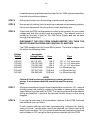
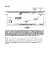
STEP 7 All signal connections (except those to automation connector J18 -- see the
following step) are made by soldering the leads to fanning strips (solder
tags) that are supplied with the CP65. The fanning strips with the soldered
wiring are fastened in place at the terminal blocks shown on the wiring
diagram.
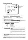
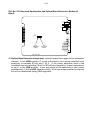
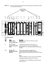
STEP 8 If you plan to make use of the automation interface in the CP65, there are
two methods you can follow.
If both remote switches and their accompanying indicators for format,
mute, and local / remote fader control are required you should use the 25
way D type connector J18. If only remote switches are required connections
can be made to TB1 using the fanning strips supplied with the CP65.