


A-Chain Alignment Procedures
Step
No.
4-8
IndicationAction
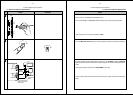
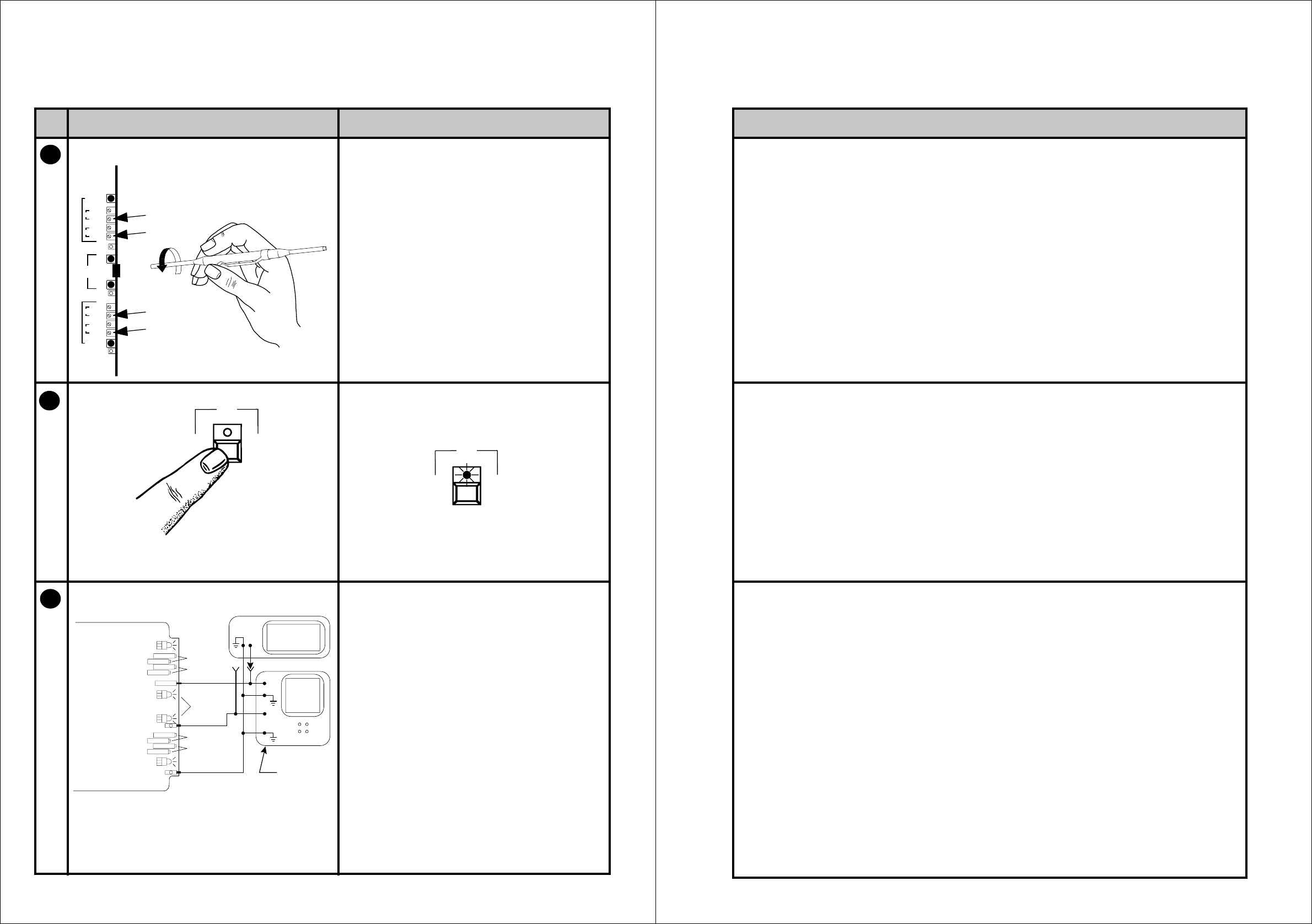
b. Optical Preamplifier Adjustments
Mono01
format
Mono01
format
4
5
6
Dolby
Rt
Lt
Lt
Rt
gnd
Proj. 2
hf
GAIN
hf
GAIN
Rt tp
Rt
Lt
Lt tp
Proj. 1
hf
GAIN
hf
GAIN
signal
present
Cat. No.
240A
Cat. No. 240A
X
Y
Proj. 1 Status
RV101 Gain
RV102 hf
RV201 Gain
RV202 hf
TP501 L tp
TP502 R tp
R
L
RV301 Gain
RV302 hf
RV401 Gain
RV402 hf
Proj. 2 Status
TP503 GND
R
R
L
L
SIGNAL
PRESENT
RTA
SCOPE
DUAL TRACE
MODE
IN
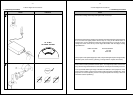
NOTE: Be sure that the vertical
range is set the same on
both channels.
A-Chain Alignment Procedures
Notes
4-9
b. Optical Preamplifier Adjustments
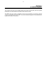
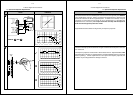
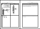
On the Cat. No. 240A Optical Preamplifier Card
Turn all of the Proj 1 and Proj 2 hf potentiometers fully counterclockwise (CCW).
Verify that power to the power amplifiers is OFF.
Press the Mono 01 format switch on the front panel; the LED in the switch should light.
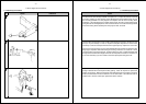
Connect the RTA and the oscilloscope to the Cat. No. 240A TP501 L (left) and TP502 R
(right) test points as shown in the interconnection diagram. Switch the scope to dual trace
mode.
Earth (ground) both instruments at TP503 GND on the card.
The input to the RTA will be switched to the left channel or right channel in the following
steps.