


7
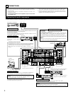
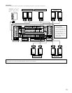
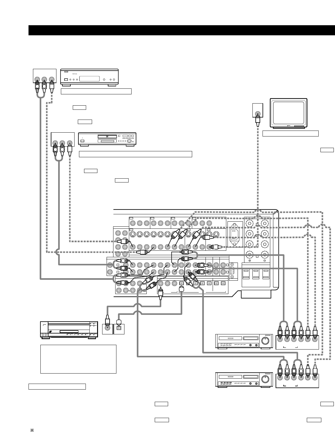
Connecting video components
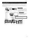
• To connect the video signal, connect using a 75 Ω/ohms video signal cable cord. Using an improper cable can result in a drop in picture quality.
• When making connections, also refer to the operating instructions of the other components.
PRE OUT
DVD TV MONITOR
YP
B/CB PR/CRYPB/CB PR/CRYPB/CB PR/CRYPB/CB PR/CR
COMPONENT
VIDEO
DBS/
SAT
AUDIO
DIGITALEXT. IN
FR FL
SW C
SR SL
SBR SBL
PHONO
CD
FRONT CENTER SB
SW
SURROUND
DVD
DVD VDP TV DBS/
SAT
V. AUX VCR-1 VCR-2 VCR-3 VCR-1 VCR-2 VCR-3
S-VIDEO
VIDEO
1-
MONITOR
-2
VDP TV
IN OUT IN
IN OUT RS-232C
OUT
PRE OUT
SPEAKER
IMPEDANCE
FRONT, CENTER,
SB / MULTI
SURROUND
A OR B
6~16Ω
6~16Ω
8~16Ω
A + B
DBS/
SAT
CDR/
TAPE
CDR/
TAPE
MULTI
ZONE
V. AUX VCR-1 VCR-2
COAXIAL
12312345 54
OPTICAL
VCR-3 VCR-1 VCR-2 VCR-3
R
L
R
L
R
L
IN
IN IN IN OUT
OUT OUT
SPEAKER SYSTEMS
AC OUTLETS
AC IN
SWITCHED TOTAL 120W (1A) MAX.
AV 120V 60Hz
FRONT
SURROUND
-A
L
L
SURROUND
-B
L
SB / MULTI
L
L
R
L
R
L
R
R
L
R
L
R OUT IN
AUDIO
VIDEO
OUT IN
LRL
R
L
R
L
R OUT IN
AUDIO
VIDEO
OUT IN
LRL
R
L
R
L
R OUT
VIDEO
OUT
L
AUDIO
L
R
R OUT
VIDEO
OUT
L
AUDIO
L
R
COAXIAL OPTICAL
OUTPUT
L
R
IN
VIDEO
B
B
TV or DBS/SAT tuner
DVD player or video disc player (VDP), etc.
Monitor TV
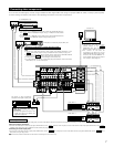
Connecting a TV, DBS/SAT tuner
TV or DBS/SAT
• Connect the TV’s or DBS/SAT tuner’s video output jack (VIDEO OUTPUT) to
the (yellow) TV,DBS/SAT IN jack using a 75 Ω/ohms video coaxial
pin plug cord.
• Connect the TV’s or DBS/SAT tuner’s audio output jacks (AUDIO OUTPUT)
to the TV or DBS/SAT IN jacks using pin plug cords.
AUDIO
VIDEO
Connecting a DVD player or a video disc player (VDP)
DVD
• Connect the video disc player’s video output jack (VIDEO OUTPUT) to the
(yellow) DVD IN jack using a 75 Ω/ohms video coaxial pin plug cord.
• Connect the video disc player’s analog audio output jacks (ANALOG AUDIO
OUTPUT) to the DVD IN jacks using pin plug cords.
• A VDP can be connected to the VDP jacks in the same way.
• It is also possible to connect a video disc player, DVD player, video camcorder,
Video Game, etc., to the V.AUX jacks.
AUDIO
VIDEO
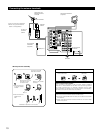
MONITOR OUT
• Connect the TV’s video input jack
(VIDEO INPUT) to the
MONITOR OUT jack using a 75
Ω/ohms video coaxial pin plug cord.
• The monitor TV can also be
connected in the same way to the
VIDEO MONITOR OUT-2 jack. Note,
however, that the AVR-4802R’s on-
screen display signals are not output
from this jack. (See page 32.)
VIDEO
Note on connecting the digital
input jacks
• Only audio signals are input to the
digital input jacks. For details, see
page 6 and page 28.
LD player or other component
equipped with digital output jacks
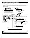
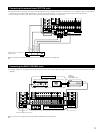
Video deck 2
Video deck 1
• There are three sets of video deck (VCR) jacks, so three video decks can be connected for simultaneous recording or video copying.
Video input/output connections:
• Connect the video deck’s video output jack (VIDEO OUT) to the (yellow) VCR-1 IN jack, and the video deck’s video input jack (VIDEO IN) to the
(yellow) VCR-1 OUT jack using 75 Ω/ohms video coaxial pin plug cords.
Connecting the audio output jacks
• Connect the video deck’s audio output jacks (AUDIO OUT) to the VCR-1 IN jacks, and the video deck’s audio input jacks (AUDIO IN) to the VCR-1
OUT jacks using pin plug cords.
Connect the another video deck to the VCR-2 or VCR-3 jacks in the same way.
AUDIOAUDIO
VIDEOVIDEO
Connecting a video decks
Connecting a Monitor TV