


Getting Started Setup Playback Remote Control Multi-zone Information Troubleshooting Specifications
R
L
R
L
"6%*0
3-
*/*/
7*%&0
"6%*07*%&0
"69
065
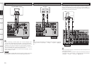
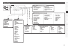
Multi-zone
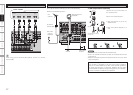
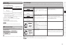
ZONE2 or ZONE3 Pre-out Connections
• If another power amplifier or pre-main (integrated) amplifier is connected, the ZONE2 or ZONE3 pre-out
(variable or fixed level) connectors can be used to play a different program source in ZONE2 or ZONE3
the same time (vpage 67 ~ 69).
• When using an S-Video cable or a video cable for connection between the AVR-2809CI and an input
device, connect to the video connectors.
• The ZONE2 video out is only for ZONE2.
Input
Output
Infrared
retransmitter
Infrared
sensor
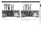
NOTE
• For the audio output, use high quality pin-plug cords so that no induction humming or noise is produced.
• For instructions on installing and operating separately sold devices, refer to the respective devices’
operating instructions.
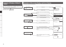
• To conduct multi-zone playback, see “Amp Assign / Multi-zone Connections and Operations” (vpage
67, 68).
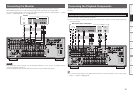
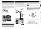
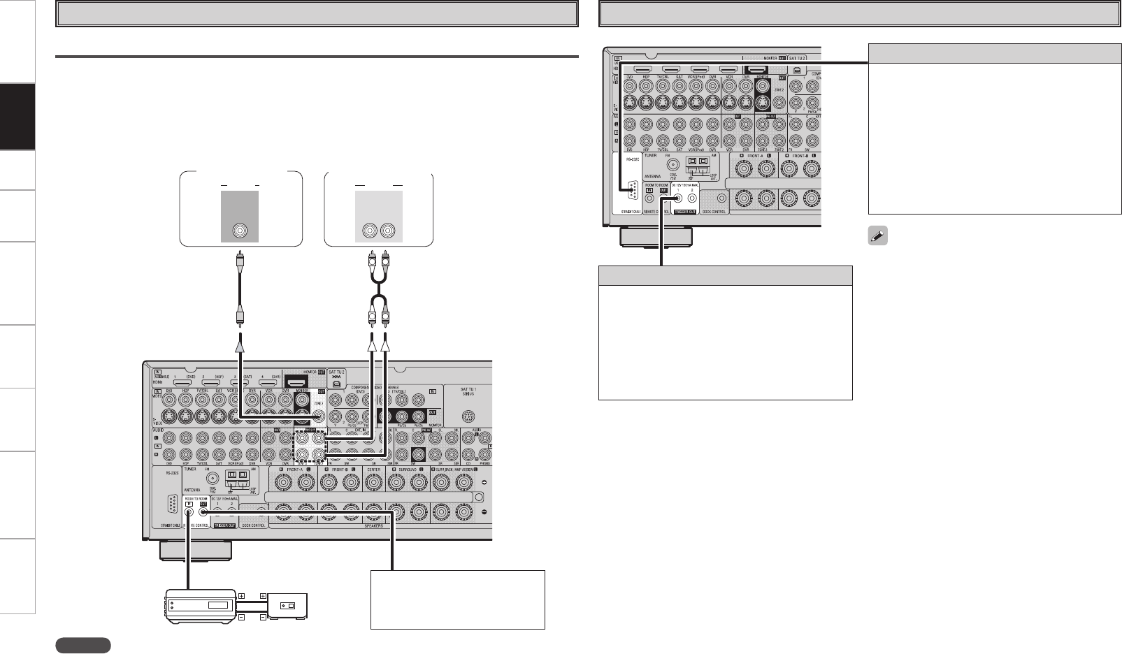
External Controller
• When using in combination with an RF Remote
Controller (RC-7000CI, sold separately) or RF
Remote Receiver (RC-7001RCI, sold separately)
two-way communication with an RF Remote
Controller is possible.
The AVR-2809CI’s status information as well as
iPod can be browsed watching the RF Remote
Controller’s display. For details, refer to the
operating instructions of the respective devices.
• When used in combination with an RF Remote
Controller or RF Remote Receiver, make the
settings at menu “Manual Setup” – “Option
Setup” – “232C Port” – “2Way Remote”
(vpage 34).
• On the menu, when setting “Manual Setup”
– “Option Setup” – “232C Port” to “2Way
Remote”, you cannot use the RS-232C connector
as an external controller (vpage 34).
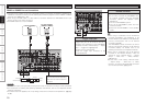
RS-232C connector
This connector is used for an external controller.
b If you wish to control the AVR-2809CI from
an external controller using the RS-232C
connector, perform the operation below
beforehand.
q Turn on the AVR-2809CI’s power.
w Turn off the AVR-2809CI’s power from the
external controller.
e Check that the AVR-2809CI is in the standby
mode.
Trigger output jack
The power of an external device equipped with
a trigger input jack can be turned on and off in
association with operations on the AVR-2809CI.
For details, see menu “Manual Setup” – “Option
Setup” – “Trigger Out” (vpage 33).
• Output: DC 12 V 150 mA MAX.
Check the trigger input conditions of the
connected device.
Monitor (ZONE2)
Extension jack for future use.
(Connect devices corresponding
with room to room function to
this jack.)
Pre-main amplier
(ZONE2 or ZONE3)
Connections