


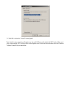
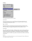
6) Select “Impedance Calibration” under the “Impedance Analyzer” menu.
The software will sweep the resistor and plot the results. The uncalibrated impedance is
displayed and the calibration is complete. You should also calibrate the test leads at this time
by selecting the appropriate command under the "Impedance Analyzer" menu and following
the on-screen instructions.
7) Connect the alligator clips from the WT3 unit to the terminals of the driver under
test.
The driver MUST NOT BE CONNECTED to an amplifier or other equipment. The connection
polarity does not matter. For the best results the driver should be clamped in place during testing. It
may be necessary to elevate drivers with vented pole pieces in order to make sure the vent is not
blocked during testing.
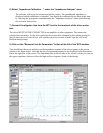
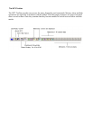
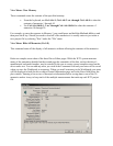
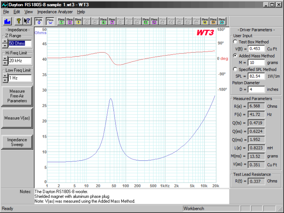
8) Click on the "Measure Free Air Parameters" button at the left of the WT3 window.
You should hear the sweep and then see the impedance response of the driver appear on the screen
similar to the figure below. Note that the driver's measured parameters are displayed in the Parameters
Bar at the right side of the screen. The Impedance Bar at the left side of the screen is where you can set
the upper impedance limit as well as the high and low frequency limits of the display.