


Using WT3 to Evaluate a Vented Box Loudspeaker
A vented box type of loudspeaker system can be characterized by it's equivalent closed box Q(tc) and
the vented enclosure's Helmholtz tuning frequency F(b). You can use WT3 to measure both of these
parameters for any vented box loudspeaker system. The frequency response of a vented box speaker is
more complex than that of a closed box being equal to the frequency response of a fourth order high-
pass filter. The characteristics of the fourth order high-pass response depend on both the equivalent
closed box response and the vent tuning frequency.
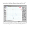
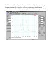
The impedance response of a typical vented box speaker is characterized by two impedance peaks in
the low frequency region. The enclosure's tuning frequency is indicated by the frequency where the
impedance is a minimum between the resonance two peaks.
Before starting, make sure the WT3 unit has been calibrated and has stabilized for at least 90 seconds.
Measure the system impedance as follows:
•
Launch the WT3 software and make sure the volume is at maximum.
•
Make sure that the speaker system is not connected to any other equipment and then connect
the test leads of the WT3 unit to the speaker under test.
•
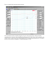
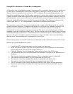
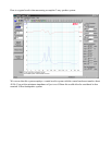
Temporarily block the speaker's vent using an airtight plug to convert the speaker to the
equivalent closed box system.
•
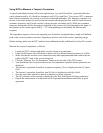
Click the "Measure Free Air Parameters" button at the left side of the WT3 screen.
•
You should hear the sweep from the speaker, the impedance is plotted and the parameters are
displayed.
•
The system's equivalent closed box resonance frequency, F(sc) is displayed in the F(s) data
field.
•
The system's equivalent closed box total Q, Q(tc) is displayed in the Q(ts) field.
•
Save the equivalent closed box data to a memory for future reference.
•
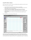
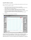
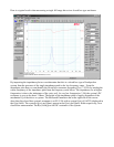
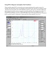
Unplug the vent and click the "Measure Free Air Parameters" button again.
•
You should hear the sweep from the speaker, the impedance is plotted.
•
Identify the two resonance peaks in the low frequency range.
•
Read the system's box tuning frequency, F(b) as the frequency at the minimum between the two
peaks.
•
The DC resistance of the system is displayed in the R(e) field. Ignore all other parameters.
•
Repeat the measurement to confirm the result. Repeated measurements should be in good
agreement.