


16
ENGLISH
Balanced audio interconnections were originally developed in the
professional audio world for preserving the delicate nuances of extremely
small microphone-level signals. For many years now, they have also been
used by performance-oriented consumer companies like Classé to preserve
every nuance of the –nest audio performances in your collection.
Technically, balanced audio interconnections provide two distinct bene–ts:
they double the signal»s strength as it travels from one component to the
next, increasing the potential signal-to-noise ratio by 6 dB; they also do an
excellent job of rejecting noise and interference that might otherwise be
picked up between the components, due to either EMI (electromagnetic
interference) or RFI (radio frequency interference). In the world of wireless
telecommunications, there is more potential interference around than ever
before—it makes sense to keep it out of music and movie soundtracks.
For this reason, we strongly recommend using balanced analog
interconnects between your Classé components wherever possible,
especially if you plan to use long interconnect cables between your
preampli–er and the power ampli–er(s) in order to minimize the length of
the speaker wires.
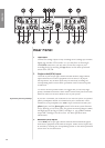
The pin assignments of these XLR output connectors are:
Pin 1: Signal ground
Pin 2: Signal + (non-inverting)
Pin 2: Signal + (non-inverting)
Pin 2: Signal + (non-inverting)
Pin 2: Signal + (non-inverting)
Pin 2: Signal + (non-inverting)
Pin 2: Signal + (non-inverting)
Pin 2: Signal + (non-inverting)
Pin 2: Signal + (non-inverting)
Pin 2: Signal + (non-inverting)
Pin 2: Signal + (non-inverting)
Pin 2: Signal + (non-inverting)
Pin 2: Signal + (non-inverting)
Pin 2: Signal + (non-inverting)
Pin 3: Signal √ (inverting)
Pin 3: Signal √ (inverting)
Pin 3: Signal √ (inverting)
Pin 3: Signal √ (inverting)
Pin 3: Signal √ (inverting)
Pin 3: Signal √ (inverting)
Pin 3: Signal √ (inverting)
Pin 3: Signal √ (inverting)
Pin 3: Signal √ (inverting)
Pin 3: Signal √ (inverting)
Pin 3: Signal √ (inverting)
Pin 3: Signal √ (inverting)
Connector ground lug: chassis ground
Connector ground lug: chassis ground
Connector ground lug: chassis ground
Connector ground lug: chassis ground
Connector ground lug: chassis ground
Connector ground lug: chassis ground
Connector ground lug: chassis ground
Connector ground lug: chassis ground
Connector ground lug: chassis ground
Connector ground lug: chassis ground
These pin assignments are consistent with the standard adopted by the
Audio Engineering Society (AES14-1992).
If you are using your Classé preampli–er with a Classé power ampli–er,
you»re all set – just take standard balanced interconnect cables and plug
them in.
If you are using another brand of power ampli–er, please refer to the
operating manual of your ampli–er to verify that the pin assignments of
its input connectors correspond to those of the CP-700. If not, have your
dealer wire the cables so that the appropriate output pin connects to the
equivalent input pin.
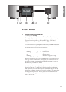
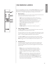
7 RS-232 Control Port
This
DB-9
connector has two purposes:
• downloading new operating software into your preampli–er
(should new features ever be added, for example)
• external control of your preampli–er by control systems such as
i-Command
™
, AMX
®
, AMX
®
, AMX
and Crestron
™
For more information, please contact your dealer and ask about home
automation systems.