


4. CONNECTIONS continued …
19
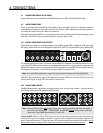
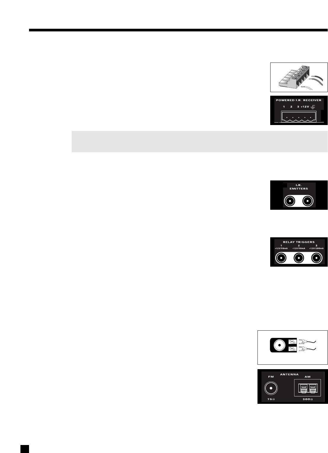
4.4 POWERED I.R. (INFRA RED) RECEIVERS
External IR repeaters allow the Remote Control to be used from other locations in
your home. Once a repeater is wired to a selected room, connect it to one of the
three I.R. RECEIVER inputs through the removable terminal block. To use the
terminal block, remove it from the AVM 30, loosen the proper screw, insert the
wire in the slot, tighten the screw onto the wire, and insert the terminal block into
the AVM 30. See section 7.4.9 for Setup information.
In addition, there is no need for an external 12V supply to power the repeaters –
use the AVM 30’s built-in supply instead for up to three repeaters, and connect
according to the repeater manufacturer’s instructions.
Note: For installers – The AVM 30’s IR inputs sense modulated 38 kHz carrier, not demodulated data.
With some control systems, an emitter face-to-face with an IR repeater may be needed.
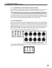
4.5 I.R. (INFRA RED) EMITTERS
External IR emitters, also known as flashers, allow control of your source
components from any location in your home that has an IR repeater wired to the
back of the AVM 30. Position a flasher in front of the source components and
connect to one of the two I.R. EMITTER outputs – IR commands coming in through
the rear I.R. RECEIVER inputs are re-transmitted through the flashers.
4.6 RELAY TRIGGERS
If your other components have provisions for a trigger, you can automatically turn
them on and off together with the AVM 30, or when a specified Source is selected.
Connect a trigger output from the AVM 30 to the trigger input of your power
amplifier, TV monitor, etc., using a cable with 3.5mm mono mini plugs.
Trigger3 is designed to provide the extra current (up to 200 mA) required by relays in larger projectors and
motorized screens. Depending on the equipment, a thicker wire gauge may be required (consult your dealer).
The AVM 30 provides flexible trigger options. From the factory, all the triggers are disabled. Through the
Setup Menu, the conditions for enabling triggers can be specified (see section 7.4.9).
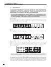
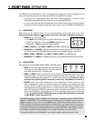
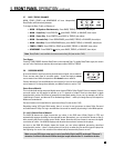
4.7 FM • AM ANTENNAS
To connect the FM antenna, first connect the two antenna wires to the
screw terminals of the 75-ohm to 300-ohm adapter. Then connect the
adapter to the FM ANTENNA connector on the AVM 30. If your local cable
company provides FM service, connect the cable directly to the AVM 30
instead of using the adapter.
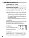
To connect the AM loop antenna, press the spring-loaded tabs of the AM
ANTENNA connector, insert the bare ends of the wire from the loop antenna
and release the tabs.
Once both antennas are connected, move each of them around until best
reception is found. For the FM antenna, this will usually be in a “T” formation.
75-ohm to 300-ohm adapter