


13
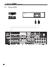
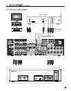
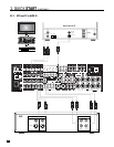
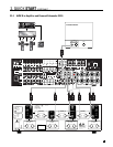
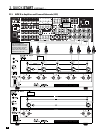
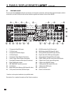
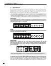
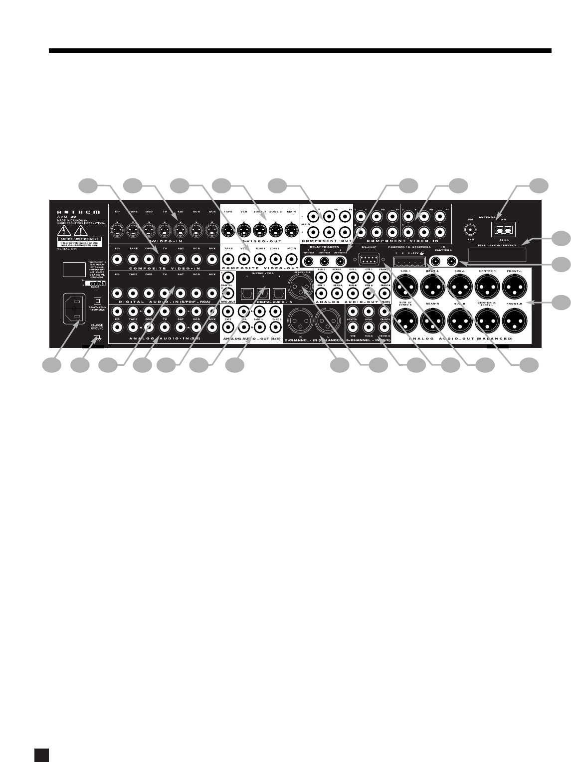
3.3 REAR PANEL LAYOUT
The rear panel of the AVM 30 contains all connections, such as power connection, audio and video inputs and outputs, antenna
connections, and the RS-232 port which allows software upgrades and external control of the AVM 30.
* Interface card requires installation by a qualified dealer.
See section 4 for complete information on Rear Panel connections.
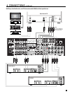
3. PANELS / DISPLAY/ REMOTE LAYOUT continued …
©©
©©
1 –7 Composite Video RCA Inputs
2 –7 S-Video Inputs
3 –5 Composite Video RCA Outputs
4 –5 S-Video Outputs
5 –2 Component Video Outputs (3 Jacks/ea)
6 –3 Relay Trigger 3.5mm Outputs (Assignable)
7 –4 Assignable Component Video Inputs (3 Jacks/ea)
8 – FM and AM Antenna Inputs
9 – IEEE 1394/PHAST Interface provision*
10 –2 I.R. Emitters
11 – MAIN Analog Audio Balanced XLR Output (10 Jacks)
12 –3 12V powered Infra Red (IR) 3.5mm Inputs
13 – RS-232 Interface Port (Bi-Directional)
14 – MAIN Analog Audio RCA Output (10 Jacks)
15 – Analog Audio 6-Channel RCA Input (6 Jacks)
16 – Digital Audio AES / EBU Input (Assignable)
17 – Analog Audio 2-Channel XLR Input (2 Jacks)
18 – ZONE2, ZONE3, and REC Analog Audio RCA Outputs
19 –3 Digital Audio Toslink Inputs (Assignable)
20 –2 Digital Audio RCA REC Outputs
21 –7 Analog Audio RCA Inputs (L/R Jacks)
22 –7 Digital Audio RCA Inputs
23 –Ground Terminal
24 – Power Cord Connection
22
23
24
21
19
18
20
131415 1216
17
7
6
8
9
10
2
4 5
1
3
11