


30 TASCAM TA-1VP
Compressor Knee Page
ª
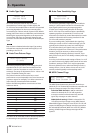
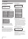
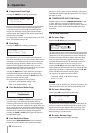
Pressing the KNEE button brings up this page:
Compressor Knee: 40
(0 is hard)
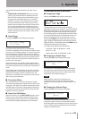
The Knee control adjusts the sharpness of the transitions
between uncompressed and compressed signals. As
a signal increases in level through the threshold, the
compressor will begin to apply gain reduction. With a
soft knee (100), that change in gain will be gradual and
therefore less noticeable.
The range of the control is from 0 (hard knee) to 100 (soft
knee). (The default setting is 48.)
Gate Page
ª
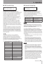
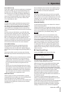
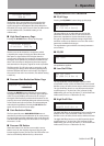
Pressing the GATE button brings up this page:
Th:-36dB_____
|
Gate Ratio: 1:20
This page allows you to set the main Gate parameters.
Use the cursor buttons to move from field to field and the
Data Knob to set each parameter. For ease in setting the
threshold, this page includes a display of the incoming
signal level and a graphic indication of the currently
selected threshold. The threshold should be set just above
the level of the signal that you wish to gate.
Pressing the GATE button again while the Gate Page is
displayed will display the Gain Reduction Meter Page
(see below). Continually pressing the GATE button will
alternate between the two pages.
The ranges of the parameters are as follows:
Threshold: –90 dB (default setting) - 0 dB
Ratio: 1:1.0 (default setting) - 1:99
Gain Reduction Meter Page
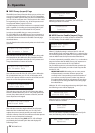
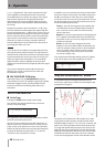
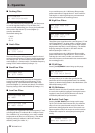
ª
C/G:-20 -12 -6 -3 0
¡¡¡¡¡¡¡¡¡¡¡
Pressing either the COMP or GATE buttons while their
respective pages are displayed will display this high
resolution gain reduction meter. The meter displays the
amount of gain reduction applied to the signal. When the
input signal is above the compression threshold or below
the gate threshold, the gain reduction meter will display
the amount of compression or gating being applied.
Pressing the COMP or GATE button again will return to
the appropriate page.
Gain Reduction Meter
ª
The front panel GAIN REDUCTION meter is intended
to provide a quick indication of compressor and gate
activity. For precise gain reduction indication, refer to the
Gain Reduction Meter Page described above. The range of
the meter is 15 dB.
COMPRESSOR/GATE ON Button
ª
When this button is lit, the COMPRESSOR/GATE module
is active. When it is not lit, the module is bypassed.
Pressing the button toggles its state. The Comp/ Gate On/
Off function can also be controlled by MIDI and/or by a
footswitch.
DE-ESSER MODULE
De-esser Page
ª
Pressing the DE-ESS button brings up this page:
This page allows you to set the main de-esser parameters.
Use the cursor buttons to move from field to field and the
Data Knob to set each parameter. For ease in setting the
threshold, this page includes a display of the incoming
high-pass signal level and a graphic indication of the
currently selected threshold. The threshold must be set
below the signal peaks for any de-essing to occur.
Pressing the DE-ESS button again while the De-esser
Page is displayed will display the De-esser Gain Reduction
Meter Page (see below). Continually pressing the DE-ESS
button will alternate between the two pages.
The ranges of the parameters are as follows:
Threshold: –60 dB - 0 dB (default setting)
Ratio: 1.0:1 - 99:1
NOTE
If you are using the Double Track function (see below), the
de-esser works on both the main and the double track.
De-esser Attack Page
ª
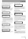
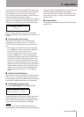
Pressing the ATK button brings up this page:
De-esser Attack
15 ms
The Attack Time control adjusts the speed with which the
de-esser’s compressor element responds to peaks in the
signal coming from the highpass filter. The range of the
control is from 0 milliseconds to 200 milliseconds. (The
default setting is 15 milliseconds.)
De-esser Release Page
ª
Pressing the REL button brings up this page:
5 – Operation