


TASCAM TA-1VP 17
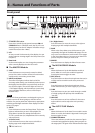
4 – Names and Functions of Parts
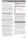
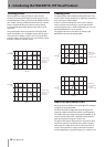
is flat and that positive correction is being applied.
Conversely, the yellow LEDs indicate that the input is
sharp and that negative correction is required.
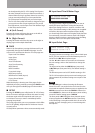
iSCALE
Press this button to select the scale to be used as
target pitches for correction.
o SPEED
Press this button to set Auto-Tune’s pitch correction
speed.
The COMPRESSOR/GATE Module
ª
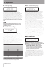
p COMP
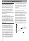
Press this button to set the compressor’s ratio,
threshold and makeup gain.
a Compressor GAIN REDUCTION Meter
This meter lights to indicate the amount of gain
reduction taking place.
s ON
When this button is lit, the Compressor/Gate module
is active.
When it is not lit, the module is bypassed. Pressing the
button toggles its state.
d ATK (Attack)
Press this button to set the compressor’s attack time.
fREL (Release)
Press this button to set the compressor’s release time.
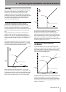
gKNEE
Press this button to set the compressor’s knee
characteristic.
h GATE
Press this button to set the gate’s ratio and threshold.
The DE-ESSER Module
ª
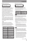
j De-esser GAIN REDUCTION Meter
This meter lights to indicate the amount of gain
reduction taking place.
kON
When this button is lit, the De-esser module is active.
When it is not lit, the module is bypassed. Pressing the
button toggles its state.
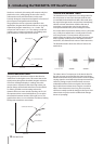
lDE-ESS
Press this button to set the de-esser’s ratio and
threshold.
; HI-PASS
Press this button to set the frequency of the de-esser’s
highpass filter.
z ATK (Attack)
Press this button to set the de-esser’s attack time.
x REL (Release)
Press this button to set the de-esser’s release time.
The EQUALIZER/OUTPUT Module
ª
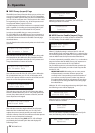
c ON
When this button is lit, both EQ bands are active. When
it is not lit, they are bypassed. Pressing the button
toggles its state.
v Output Level Meter
This meter displays the TA-1VP’s output level..
b ON
When this button is lit, double tracking is active. When
it is not lit, it is bypassed. Pressing the button toggles
its state.
nEQ BAND 1
Press this button to select the type of equalization and
the parameter values for parametric EQ band #1.
m DBL (Double) TRACK
Press this button to select the type and amount of
automatic double tracking.
, EQ BAND 2
Press this button to select the type of equalization and
the parameter values for parametric EQ band #2.
. OUT GAIN
Press this button to adjust the TA-1VP’s output gain
and/or to engage the main bypass.
NOTE
While main bypass is engaged, no other controls will
respond until bypass is disengaged.
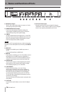
/+48V Indicator
This LED lights when Phantom power for the XLR MIC
IN input has been turned on in the setup menu.
!MIC IN
This XLR connector is where a microphone can be
connected to the TA-1VP. The TA-1VP can supply 48V
phantom power for condenser microphones (turned
this on in the setup menu). Either the MIC IN or LINE
IN input can be selected for processing, but not both
at the same time.
Line level signals should be connected to the rear
panel 1/4” LINE IN connector.
@–20dB
This is a latching push button to engage a 20 dB pad
into the XLR Microphone signal path. This lets you use
the TA-1VP with loud sources.