


16 TASCAM TA-1VP
4 – Names and Functions of Parts
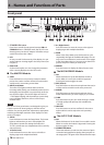
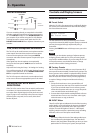
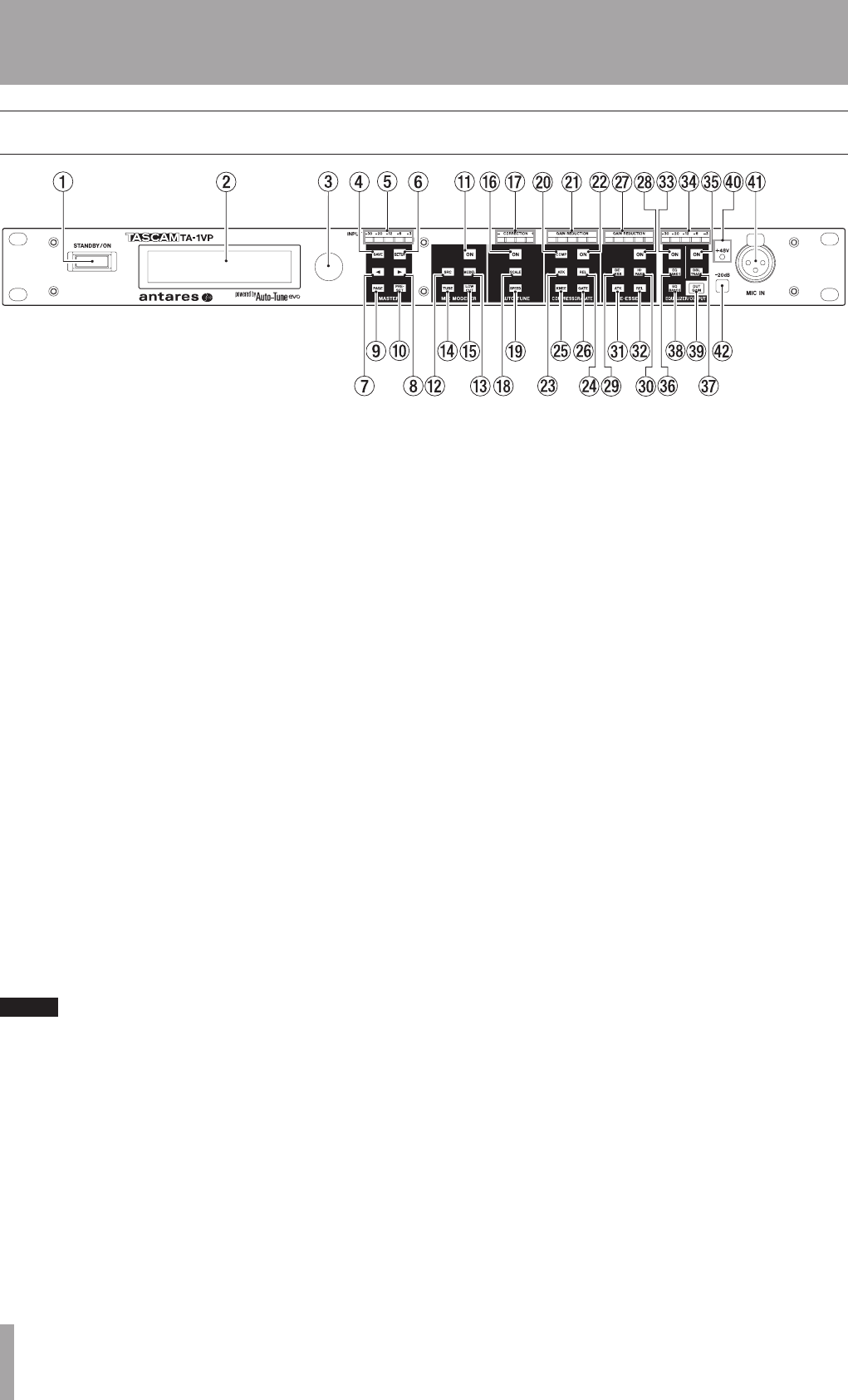
Front panel
1 STANDBY/ON button
Press this to switch the unit power between ON and
STANDBY. When in STANDBY mode, the TA-1VP is not
drawing power, but the AC Adapter will still be using a
small amount (less than 1 Watt)
2 LCD
An easy-to-read 20 character by 2 line display. You can
set the optimum viewing angle in the Setup menu (See
Chapter 5).
3 Data Knob
As the name implies, turn it to change the parameter
value currently displayed on the LCD screen.
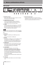
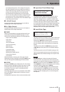
The MASTER Module
ª
4 SAVE
Press this button to save a newly created or edited
preset. Also used to confirm choices in functions that
would result in overwriting current data.
5 INPUT Level Meter
These five LEDs light to indicate the level of the
incoming audio. Ideally, you should adjust the input to
the highest level that does not consistently cause the
top red LED to light. (The red LED lights at a level of
–3 dB. Digital clipping, which introduces a particularly
nasty-sounding distortion, will occur if the input
exceeds 0 dB.)
NOTE
The TA-1VP’s front panel meters are designed to give you
a quick overview of what’s going on with the various
modules. For precise parameter adjustments, appropriate
modules provide high resolution meter displays on their
various LCD pages.
6 SETUP
Press this button to enter the Setup Menu. The button
lights to indicate that you are in Setup Mode. The
Setup Menu contains the settings that affect the
TA-1VP’s overall state (i.e., independent of the currently
selected Preset).
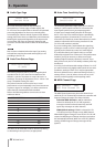
7 Ó (Left Cursor)
Press this button to move the cursor to the left on
display pages with multiple data fields.
8 Á (Right Cursor)
Press this button to move the cursor to the right on
display pages with multiple data fields.
9 PAGE
When in the Setup Menu, press this button to cycle
sequentially through the available edit pages. You can
only move in one direction, but there are so few pages
in the Setup Menu that you are never more than a few
presses away from where you want to be.
0 PRESET
Press this button to display the Select Preset screen.
The MIC MODELER Module
ª
q ON
When this button is lit, the Mic Modeler module is
active. When it is not lit, the module is bypassed.
Pressing the button toggles its state.
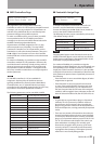
w SRC (Source)
Press this button to select the microphone that was (or
will be) used to record the audio to be processed.
eMODEL
Press this button to select the microphone whose
audio characteristics you wish to apply to your audio.
r TUBE
Press this button to pass your audio through a model
of a high-quality tube preamp with variable tube
“warmth.”
t LOW CUT
Press this button to set low cut filters for the source
and model mics and to adjust the mics’ proximity
effects.
The AUTO-TUNE Module
ª
y ON
When this button is lit, the Auto-Tune module is active.
When it is not lit, the module is bypassed. Pressing the
button toggles its state.
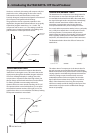
uCORRECTION Meter
This meter indicates, in real time, the amount of pitch
correction being applied to change the input pitch to
the target pitch. The green LEDs indicate that the input