


5-43
Servicing
Adjustment Procedures
j
Press
user pattern
and then
INTERNL PATT 1
.
8
Adjust the
ECL –1 ADJ
potentiometer so that the optical power measures
+1.5 dBm.
9
On the pattern generator, press the left-side
select pattern
softkey.
10
Press the
2
23
–1
softkey.
11
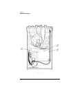
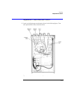
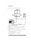
Locate the test points that are labeled “
P4
” on the A2 Main Board Assembly.
Measure the voltage across pins 15 and 16 (
LOOP test
points).
12
Adjust the
DRIVE ADJ
potentiometer so that the voltage measured across pins 15
and 16 varies less than 20 mV when the pattern generator signal is present and
then removed.
13
Disconnect the pattern generator signal from the Agilent 83430A.
14
Press the front-panel
SELECT
key so that the
ANALOG IN AC COUPLED
connector is
selected. No signal should be connected to this input.
15
Adjust the
ANALOG BIAS
potentiometer so that the optical power measured at
the front-panel
OPTICAL OUT
connector is –1.5 dBm ±0.2 dB.
16
Turn the Agilent 83430A’s
LINE
switch off.