


2-4
Making Measurements
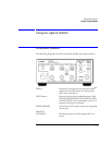
Using the Agilent 83430A
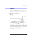
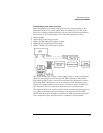
DIGITAL IN (AC COUPLED)
Modulation input for digital signals. The input is
AC coupled. BNC connector.
DIGITAL IN
(DC COUPLED)
Modulation input for analog signals. This input is
DC coupled. BNC connector.
WAVELENGTH ADJUST
knob Allows you to adjust the laser’s wavelength when
the variable mode is activated. Press the
PRESET/
VARIABLE
button so that the front-panel light
turns on.
PRESET/VARIABLE
button Toggles between preset laser wavelength or
amplitude settings. (Light turns on to indicate
you can adjust the setting using the knob.).
BIAS ADJUST
knob Allows you to adjust the laser’s output amplitude
when variable mode is activated. Press the
PRE-
SET/VARIABLE
button so that the front-panel light
turns on.
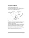
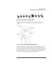
OPTICAL OUT
connector This connector provides the instrument’s laser
output. A universal adapter is used that can be
removed and replaced with different adapters as
needed (refer to “Front-Panel Fiber-Optic
Adapters” on page 4-4).