5-26
Servicing
Performance Tests
Test 6. STM-16/OC-48 Conformance
1
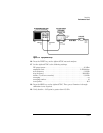
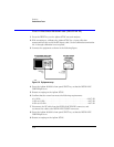
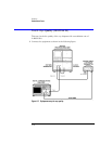
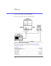
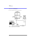
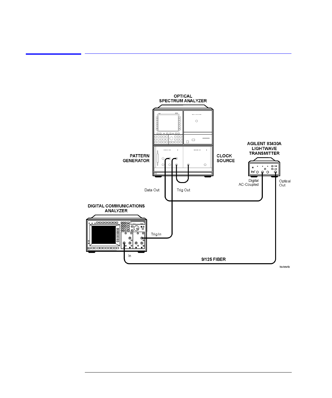
Connect the equipment as shown in the following figure.
Figure 5-8. Equipment setup for eye quality
2
Set the pattern generator to the following settings. For step-by-step
instructions on setting these values, refer to “Configuring the pattern
generator” on page 5-35.
data pattern. . . . . . . . . . . . . . . . . . . . . . . . . . . . . . . . . . . . . . . . . . . . . . . . . . 2
23
–1
data amplitude (ECL). . . . . . . . . . . . . . . . . . . . . . . . . . . . . . . . . . . . . 850 mV p-p
data output high level (ECL). . . . . . . . . . . . . . . . . . . . . . . . . . . . . . . . . –900 mV
data termination . . . . . . . . . . . . . . . . . . . . . . . . . . . . . . . . . . . . . . . . . . . . . . . –2 V
clock trigger . . . . . . . . . . . . . . . . . . . . . . . . . . . . . . . . . . . . . . . . . . . . . . . . . . . on
trigger mode . . . . . . . . . . . . . . . . . . . . . . . . . . . . . . . . . . . . . . . . . . . .CLOCK / 23
trigger pattern. . . . . . . . . . . . . . . . . . . . . . . . . . . . . . . . . . . . . . . . . . . . . .23 zeros
clock rate. . . . . . . . . . . . . . . . . . . . . . . . . . . . . . . . . . . . . . . . . . . . . . 2.48832 GHz
clock amplitude. . . . . . . . . . . . . . . . . . . . . . . . . . . . . . . . . . . . . . . . . . . . . 850 mV


