


TX6n/5n/4n Reference Manual
7
Controls and Connectors
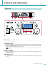
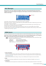
!3 Encoders A, B
When the display shows the attenuation meter, these encoders adjust the attenuation of channels A and B. If any other
screen is displayed, encoder A moves the cursor and encoder B modifies the parameter value.
• Only encoder A can be operated if you’re adjusting the attenuation when the amplifier mode is Bridge.
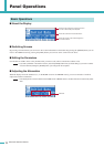
!4 Display
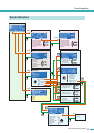
This shows the amplifier’s settings or a level meter. Refer to “Screen Structure” (page 13) for details.
• If the power supply is in Standby mode or if the LCD Setup’s Backlight setting is Auto OFF, the backlight will go dark if no
panel operation has been performed for ten seconds. It will light again when a panel operation is performed.
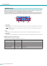
!5 Function buttons
These buttons move to the screen indicated above each button in the display. If a channel name (e.g., CH A, CH B) is
shown, this means that a parameter for that channel is displayed; press the corresponding function button to switch the
channel that is shown. These buttons may also operate in different ways depending on the screen shown in the display.
!6 [HOME] button
This accesses the HOME screen (page 15) in the display.
By holding down this button for three seconds or longer, you can switch the power between Standby and On modes. When
the confirmation message appears, press the [ENTER] button to switch the setting.
!7 [EXIT] button
By pressing this button when the display shows a screen other than the HOME screen, you can move to the screen of the
next highest level.
•To temporarily disable panel lock, simultaneously hold down the [HOME] button and [EXIT] button for three seconds or
longer.
• If you hold down this button for three seconds or longer in the HOME screen, the FAULT OUTPUT connector output will
be reset (NC and C will be connected).
!8 [ENTER] button
Use this to select a parameter or to finalize an edited parameter value. Depending on the screen shown in the display, this
button may also be used in other ways. If the parameter value is blinking, you must finalize the value by pressing this but-
ton.
• If you hold down this button for one second or longer in the HOME screen, the UTILITY screen Device Setup page (page
19) will appear.
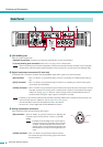
!9 Air intakes
The amplifier uses forced-air cooling. The variable speed cooling fan draws air in from the front and exhausts it through the
rear. The cooling fan speed varies depending on the heat sink temperature: It operates at low speed when it is below 40 °C
(40%), increases in speed according to increases in temperature, and operates at high speed when temperature exceeds 60
°C (60%). If the power supply exceeds 90°C, the variable speed fan will operate at high speed regardless of the heat sink
temperature.
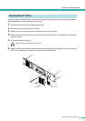
Please be sure that you do not block the air intakes or exhaust vents. Also, clean the filter elements regularly. If the air
intakes are clogged with dust or debris, the amplifier will overheat, which may result in the amplifier shutting down.
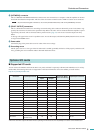
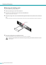
@0 Screw holes for handles
These four screw holes (four locations) are for the included handles. Fix the handles to the amplifier, using the included flat-
head screws.
NOTE
NOTE
NOTE
NOTE