


TX6n/5n/4n Reference Manual
59
Appendix
L
L.SHELF .......................................................................38
Label.............................................................................19
Last Memory Resume...................................................23
LCD Setup ....................................................................22
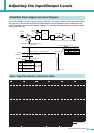
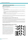
Level adjustment...........................................................53
Level diagram ...............................................................53
Level meter...................................................................16
Library.......................................................................4, 32
Limiter.....................................................................29, 39
Limiter Gain Reduction .................................................29
LPF ...............................................................................38
M
MAC Address................................................................21
MENU screen ...............................................................24
Message list..................................................................55
METER screen .............................................................16
Misc Setup....................................................................24
[MUTE] button.................................................................6
[MUTE] indicator.............................................................6
MUTE Key ....................................................................22
Mute On/Off ..................................................................38
MY cards.........................................................................9
N
[NETWORK] connector.............................................9, 51
[NETWORK] indicator.....................................................5
Network Setup ..............................................................21
O
Optional cards.................................................................9
Oscillator Mix ................................................................35
Output Delay.................................................................37
Output Level .................................................................38
Output Router ...............................................................39
Output Signal Chain......................................................27
Override........................................................................26
P
Panel.............................................................................22
Panel Operations..........................................................12
Parallel..........................................................................25
[PARALLEL] indicator.....................................................6
Peak Hold .....................................................................18
PEQ ..............................................................................38
Power cable....................................................................9
Power Limiter................................................................29
[POWER] switch and indicator........................................5
[PROTECTION] indicator................................................6
R
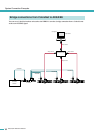
Redundant connections................................................46
Remote control .............................................................51
S
Scene........................................................................4, 40
Scene Recall.................................................................23
Scene screen................................................................40
Scene Setup .................................................................23
Screen categories.........................................................14
Screen structures..........................................................13
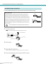
Screw holes for handles .................................................7
Sensitivity..........................................................25, 53, 54
Sensitivity/Amp Gain.....................................................25
Serial No.......................................................................21
SETTING screen ..........................................................17
Setup ..............................................................................3
Signal Chain .................................................................27
[SIGNAL] indicator..........................................................6
SIGNAL PATH screen ..............................................4, 30
Slot Input Router...........................................................33
Slot Input Signal Chain .................................................27
SLOT INPUT VOLTAGE...............................................16
SLOT OUTPUT METER...............................................16
SP OUTPUT IMPEDANCE...........................................16
SP OUTPUT POWER...................................................16
SP OUTPUT VOLTAGE ...............................................16
Speaker Processor .................................................32, 35
[SPEAKERS] jacks .........................................................8
Standby.........................................................................25
[STANDBY] indicator ......................................................5
Standby/On...................................................................25
Stereo ...........................................................................25
Stereo/Bridge/Parallel...................................................25
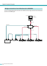
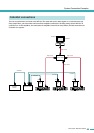
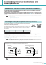
System Connection Examples......................................44
T
Terms..............................................................................4
THERMAL.....................................................................16
Troubleshooting............................................................57
U
Unit ...............................................................................18
UTILITY screen.............................................................19
V
Version..........................................................................21
Voltage Limiter..............................................................29
W
Word Clock Setup.........................................................20
X
X-Over ..........................................................................36
X-Over Input Level........................................................35
X-Over Polarity .............................................................35