


TX6n/5n/4n Reference Manual
14
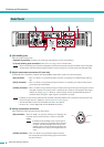
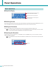
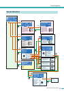
Panel Operations
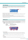
*Scene..........The settings listed above, such as Standby/Power-On or mute (with the exception of UTILITY), are called a “scene”. By recalling a scene, the
saved settings can be immediately applied to the amplifiers.
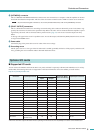
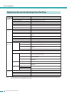
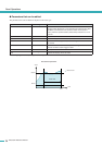
Operations that can be Performed from the Panel
Category Subcategory Explanation
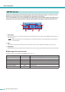
METER
(page 16)
ANA INPUT VOLTAGE Shows the input level from the analog input connectors.
SLOT INPUT VOLTAGE Shows the input level from the slot.
SP OUTPUT VOLTAGE Shows the output level from the [SPEAKERS] connectors.
SP OUTPUT POWER Shows the output power from the [SPEAKERS] connectors.
SP OUTPUT IMPEDANCE Shows the output impedance from the [SPEAKERS] connectors.
SLOT OUTPUT METER Shows the output level to the slot.
THERMAL Shows the heat sink temperature.
UTILITY
(page 19)
Device Setup Makes settings to distinguish the amplifier on a network.
Word Clock Setup Sets the word clock.
Information Shows information about the amplifier.
Network Setup Specifies the IP address and other settings for using the amplifier in a
network.
LCD Setup Specifies the display settings.
Front Panel Operation Turns panel operation lock on/off.
Scene Setup Makes scene* settings.
Misc Setup Sets the amplifier’s internal clock, etc.
MENU
(page 24)
General Sensitivity/Amp Gain Sets the input sensitivity/gain.
Stereo/Bridge/Parallel Specifies the amplifier’s mode (Stereo/Bridge/Parallel).
Attenuation Link Specifies whether attenuator operation will be linked between channels
A and B.
Input Redundancy Specifies the redundant connection mode, etc.
Signal Path Makes settings for the equalizer, delay, crossover, and others that pro-
cess the audio signal. Speaker Processor libraries can also be recalled.
Signal Chain Analog Input Signal Chain Makes settings for checking whether the audio signal is being correctly
input from the analog connectors.
Slot Input Signal Chain Makes settings for checking whether the audio signal is being correctly
input from the slot.
Output Signal Chain Makes settings for checking the status of output from the [SPEAKERS]
connectors.
Calibration Calibrate by Pilot Tone Uses a pilot tone to measure the impedance of the connected speakers.
Calibrate by Prog Source Uses an audio signal to measure the impedance of the connected
speakers.
Limiter Voltage Limiter Makes settings for the limiter.
Power Limiter
Limiter Gain Reduction Specifies whether the limiter will be linked between channels A and B.
SCENE
(page 40)
Recall Recalls a scene*.
Store Stores a scene*.
Edit Edits a scene*.
Clear Clears a scene*.