


TX6n/5n/4n Reference Manual
26
Panel Operations
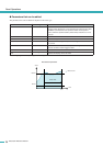
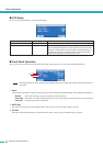
● Input Redundancy
Here you can make settings for a redundant connection (duplicate audio connections) that uses both the analog input signal and
the digital (slot) input signal. If the digital input audio is interrupted by a broken connection or other problem, the amplifier can
automatically switch to the analog input (Backup), or the amplifier can automatically switch to the analog input simply when an
analog audio input signal is detected (Override).
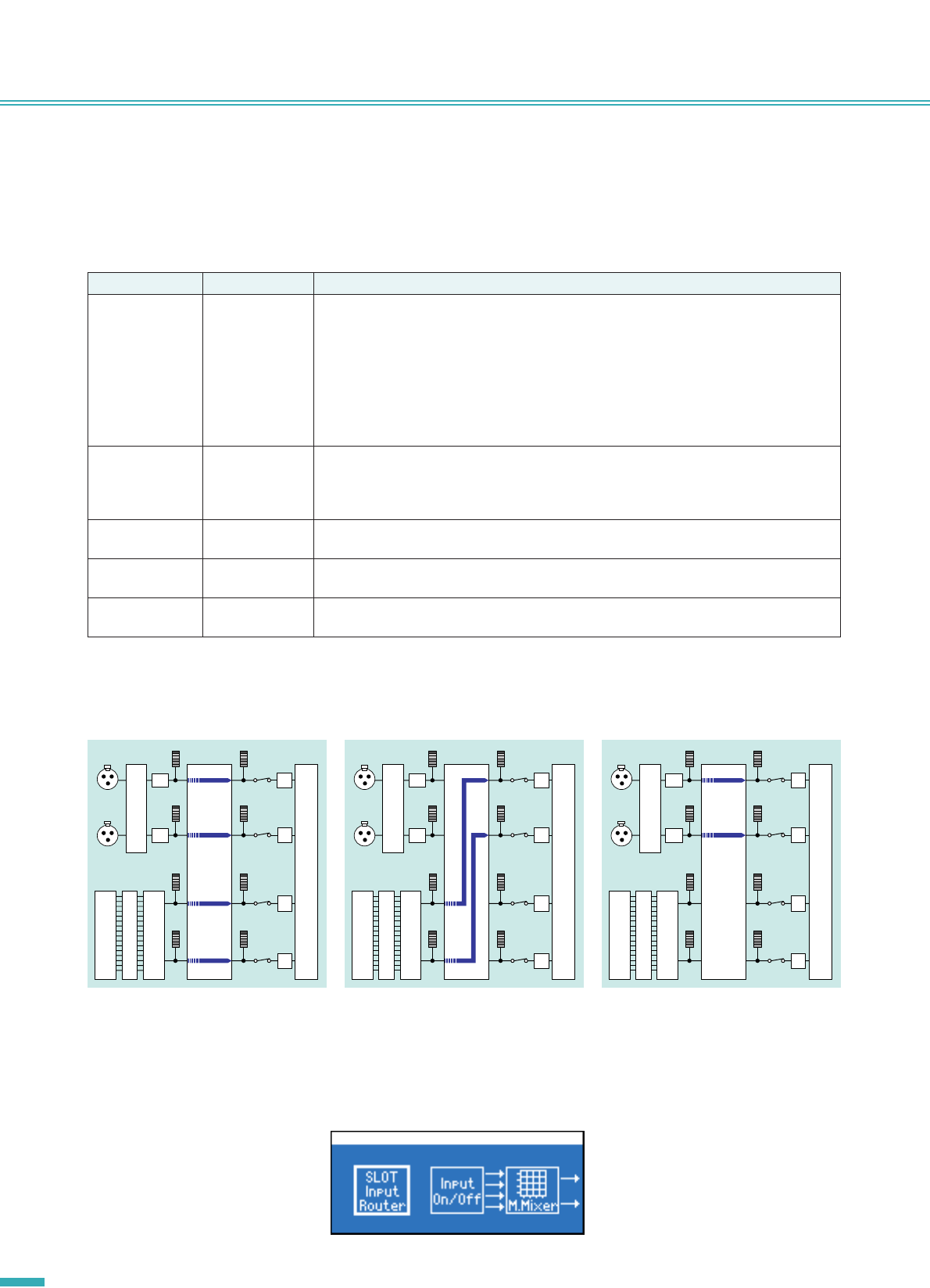
■ Signal Path
Refer to the “SIGNAL PATH Screen” (page 30).
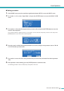
Parameter name Range Explanation
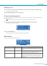
Mode OFF, Backup,
Override
Specifies the redundant connection mode.
Backup : The input signal from the card installed in the slot will be the main signal; if the
input from the card becomes unlocked, the amplifier will automatically switch
to the input from the analog jack. Refer to “Supported I/O cards” (page 9) to
check if your I/O card supports the Backup mode.
Override : The input signal from the card installed in the slot will be the main signal; if
input from the analog jack is detected, the amplifier will automatically switch to
the input from the analog jack.
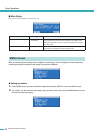
Auto Return ON/OFF When using Backup mode, this specifies whether the slot input will be re-enabled when the
interrupted slot input has recovered.
When using Override mode, this specifies whether the slot input will be re-enabled when the
analog input is interrupted.
Ovrrid Ch Link ON/OFF When using Override mode, this specifies whether both channels will switch together (ON) or
separately (OFF) when analog input is detected as being present or absent.
Ovrrid Thrsld -30.0–0.0 dBFS When using Override mode, this specifies the input level threshold value used to determine
the presence or absence of analog input.
Auto Rtn Delay 0–60 s When using Override mode with Auto Return ON, this specifies the time from when an inter-
ruption in the analog input is detected until the amplifier switches to the digital input.
Redundancy
Gain/
Sens.
[Analog
Input A]
[Analog
Input B]
ADC
Matrix
Mixer
Slot
Input
Router
Pol.
Pol.
Pol.
Pol.
ADC
Gain
Redundancy
Gain/
Sens.
[Analog
Input A]
[Analog
Input B]
ADC
Matrix
Mixer
Pol.
Pol.
Pol.
Pol.
ADC
Redundancy
Gain/
Sens.
[Analog
Input A]
[Analog
Input B]
ADC
Matrix
Mixer
Pol.
Pol.
Pol.
Pol.
ADC
Slot
Input
RouterGain
Slot
Input
RouterGain
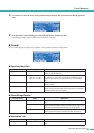
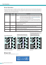
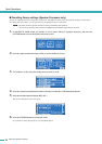
●
Input Redundant OFF
●
Backup mode (normal state)
●
Override mode (normal state)
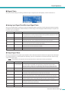
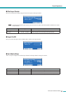
●
When digital input signal becomes
unlocked in Backup mode
●
When analog input signal is
detected in Override mode
Both of the analog and digital signals are
input into the 4x4 Matrix Mixer.
Only the digital signal is input into the 4x4
Matrix Mixer.
Only the analog signal is input into the 4x4
Matrix Mixer.