


TX6n/5n/4n Reference Manual
51
Connecting External Controllers and
Analog Devices
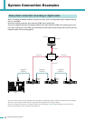
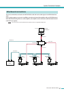
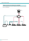
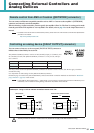
You can connect an Ethernet-compatible controller such as AMX or Crestron to the amplifier’s [NETWORK]
connector, and remotely control the amplifier.
When connecting a remote controller, you must specify the amplifier’s Port No. The Port No. setting can be made
from the panel of the TXn amplifier or via Amp Editor. For details, refer to page 21 or to the Amp Editor owner’s
manual.
•For details of the remote control communication protocol, please refer to the “TXn Remote Control Protocol Specification”
provided on the website.
http://www.yamahaproaudio.com/
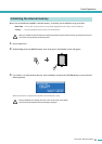
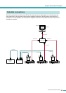
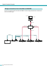
You can connect a lamp etc. to the rear panel [FAULT OUTPUT] connector to
indicate that an abnormality has occurred.
The [FAULT OUTPUT] connector consists of NO (Normally Open), C (Common), and
NC (Normally Closed). The [FAULT OUTPUT] connector is a relay circuit, and oper-
ates as follows.
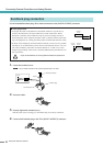
The relay contacts used in the [FAULT OUTPUT] connector are rated for a load of 1A, DC 30V. Do not apply a load that
exceeds this rating.
Use Amp Editor to make settings for the [FAULT OUTPUT] connector.
Euroblock plugs are used for the [FAULT OUTPUT] connector. Euroblock connection methods are described in “Euroblock
plug connection” (page 52) in this manual.
• In Amp Editor’s [Device Setup] menu ➝ [Alert Setup], you can set Type to Fault so that a fault can be indicated by a con-
nected lamp, etc. For details on making settings, refer to the “Amp Editor owner’s manual.”
• The relay contacts are rated for a resistive load of 1A, DC 30V. Do not apply a load that exceeds this rating.
Remote control from AMX or Crestron ([NETWORK] connector)
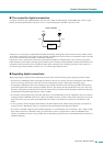
Controlling an analog device ([FAULT OUTPUT] connector)
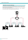
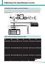
Normal state Abnormal state Powered-off
NO Open Closed Closed
NC Closed Open Open
● Example : Using an LED to indicate normal/fault status of the TXn
NOTE
NOTE
C
NC
NO
C
NC
NO
Normal state
Lit
Powered-off / Abnormal state
TXn TXn
Unlit
Unlit
Lit
CAUTION