


E-15
English
ANTENNA
FM
75
Ω
UNBAL.
GND AM
ANTENNA
FM
75
Ω
UNBAL.
GND AM
(1)
(2)
(3)
(4)
ANTENNA
FM
75
Ω
UNBAL.
GND AM
or
Earth rod
7.5 m (25 feet)
15 m (49 feet)
ANTENNA
FM
75
Ω
UNBAL.
GND AM
VIDEO
SIGNAL
TO SW-AV1
AUDIO
OUTPUT
IN
MONITOR OUT
VIDEO 1
OUT IN
VCR
OUT IN
TAPE/MD
MARK
SYSTEM
CONNECTOR
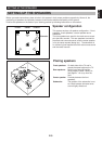
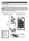
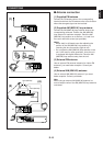
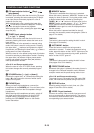
■ Antenna connection
(1) Supplied FM antenna
Connect the FM antenna wire to the corresponding
terminal and direct the FM antenna wire to the direction
where the strongest signal can be received.
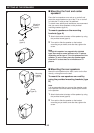
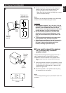
(2) Supplied AM (MW/LW) loop antenna
Connect the AM (MW/LW) loop antenna wires to the
corresponding terminals. Position the AM (MW/LW)
loop antenna for optimum reception. Place the AM
(MW/LW) loop antenna on a shelf etc., or install it on
the rack or wall with screws (not provided).
Notes
•
When static is still heard even after adjusting the
position of the AM (MW/LW) loop antenna, try
reversing the wire connections (right to left).
•
Do not place the AM (MW/LW) loop antenna on the
unit. It will result in noise generation, since the unit
is equipped with digital electronics. Place the AM
(MW/LW) loop antenna away from the unit.
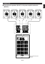
(3) External FM antenna
Use an external FM antenna instead of an indoor FM
antenna if you need better reception. Consult your
dealer.
(4) External AM (MW/LW) antenna
Use an external AM (MW/LW) antenna if you need
better reception. Consult your dealer.
Note
When using an external AM (MW/LW) antenna, be
sure to keep the wire of the AM (MW/LW) loop antenna
connected.
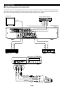
CONNECTIONS