


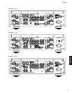

A-S2000
9
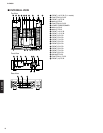
■ DISASSEMBLY PROCEDURES /
(Remove parts in the order as numbered.)
Disconnect the power cable from the AC outlet.
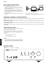
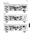
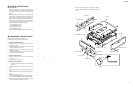
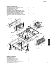
1. Removal of Panel Side L/R
a. Remove 2 screws (1), 2 coned disc spring L and 2
washers side. (Fig. 1)
b. Lift the panel side L a little and release 3 hooks. Then
remove the panel side L. (Fig. 1)
c. Remove 2 screws (2), 2 coned disc spring L and 2
washers side. (Fig. 1)
d. Lift the panel side R a little and release 3 hooks. Then
remove the panel side R. (Fig. 1)
2. Removal of Top Cover
a. Remove 7 screws (3), 2 screws (4) and 2 screws
(5). (Fig. 1)
b. Remove the top cover. (Fig. 1)
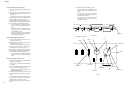
3. Removal of Front Panel
* Prepare a hexagonal wrench (2 mm) for removal of
knob unit.
a. Loosen lock set screw to remove the knob VOL unit.
(Fig. 1)
b. Loosen lock set screw to remove the knob SEL unit.
(Fig. 1)
c. Loosen each lock set screw to remove 3 knob TC unit.
(Fig. 1)
d. Remove 8 screws (6). (Fig. 1)
e. Set the “POWER ON/OFF” switch to the ON position.
f. Set the “PHONO MM/MC” switch to the MM position.
g. Remove the front panel forward gradually using care
not to cause damage the switches. (Fig. 1)
1
2
3 4 5
6
Panel side L
Panel side R
Washer side
Washer side
Coned disc spring L
Coned disc spring L
Front panel
Top cover
6
6
3
1
3
4
5
2
Hook
Hook
POWER ON / OFF switch
PHONO ON / OFF switch
Hook
Knob VOL unit
Hexagonal wrench
Knob SEL unit
Knob TC unit
2mm
Lock set screw
Fig. 1
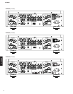
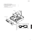
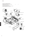
■ SERVICE PRECAUTIONS /
Safety measures
• Some internal parts in this product contain high volt-
ages and are dangerous. Be sure to take safety mea-
sures during servicing, such as wearing insulating
gloves.
• Note that positions indicated below are dangerous even
after the power is turned off because an electric charge
remains and a high voltage continues to exist there.
Before starting any repair work, perform discharge by
connecting a discharge resistor (5k-ohms/10W) be-
tween terminals at following positions. The time re-
quired for discharging is about 30 seconds.
1. C308 on MAIN (3) P.C.B..
2. C309 on MAIN (3) P.C.B..
3. C335 on MAIN (3) P.C.B..
4. C336 on MAIN (3) P.C.B..
Refer to “PRINTED CIRCUIT BOARDS: MAIN (3) P.C.B.”.
* When installing the knob unit, it is necessary to position
them as specified. (Refer to “When installing the knob
unit”.)