


W1003
W1002
W1001
A
1
2
3
4
5
6
7
8
9
10
BCDEFGH I JK
L MN
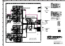
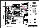
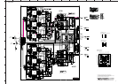
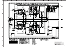
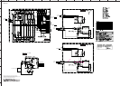
A-S2000
65
★ All voltages are measured with a 10MΩ/V DC electronic voltmeter.
★ Components having special characteristics are marked s and must be replaced
with parts having specifications equal to those originally installed.
★ Schematic diagram is subject to change without notice.
FRONT 2/3
0
10.6
0.6
0
-10.5
-0.6
0
-10.5
-0.6
0
-10.5
-0.6
0
-10.5
-0.6
10.6
0
0.6
10.6
0
0.6
10.6
0
0.6
10.6
0
0.6
-10.5
-0.5
-0.5
0
-10.5
-0.5
-0.5
0
-0.5
0
-10.5
0
-0.5
0
10.6
0.6
0
10.6
0.6
0
10.6
0.6
25.1
24.2
24.7
24.6
0.8
25.2
0.8
24.2
0.7
25.2
0.7
24.7
24.7
24.6
25.1
24.2
25.1
24.6
24.4
25.1
24.4
24.2
24.6
5.4
24.2
6.0
6.0
0
6.0
-0.1
0.1
5.5
5.4
0.1
-0.7
-24.7
0.7
-0.1
-25.2
-0.7
-0.1
-25.3
0.8
25.7
0.2
0.7
25.7
0.2
24.2
-24.7
-25.2
-0.7
-24.7
25.2
-24.6
-24.2
-11.8 -11.8
-11.8 11.9
-11.8 11.9
20.9 25.7
-25.2
-20.7
20.9 25.7
-20.7
00
0
0
0.6 0.6
0.5
0.5
0.6
-0.5
0.1
0
6.0
0.1
0.1
5.5
5.4
0
24.6
0.1
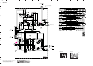
FRONT (10)
PHONO
to FUNCTION (1)_CB301
Page 60
B3
to FRONT (11)_CB27
Page 66
G3
to FUNCTION (1)_CB305
Page 60
K9