


16
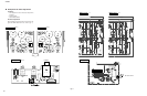
A-S2000
A-S2000
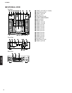
F G
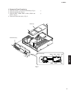
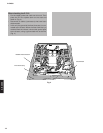
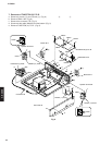
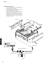
7. Removal of FUNCITON (2) P.C.B.
a. Remove 4 screws (F) and a screw (G). (Fig. 8)
b. Remove CB401-404. (Fig. 8)
c. Remove the connector TR. (Fig. 8)
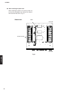
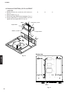
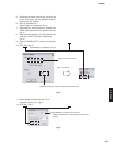
d. Disconnect the cable (W4004) from the bottom. (Fig. 9)
e. Remove FUNCTION (2) P.C.B.. (Fig. 8)
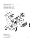
Fig. 8
N
N
H
H
F
F
G
I
L
Q
R
R
O
P
J
K
M
M
CB27
CB201
CB202
CB203
CB401
CB23
CB2
CB79
CB59
CB402
CB403
CB404
Frame side R
Connector TR
Solder
Barrier SP R
Barrier SP L
Speaker terminal L
Speaker terminal R
FUNCTION (2) P.C.B.
FUNCTION (3) P.C.B.
BALANCE P.C.B.
FRONT (11) P.C.B.
FRONT (13) P.C.B.
FRONT (12) P.C.B.
Solder