


13
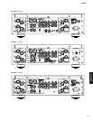
A-S2000
A-S2000
A
A
0
9
9
9
B
B
C
C
D
D
D
D
D
E
E
CB52
CB21
CB22
CB24
CB26
CB73
CB76
CB74
CB72
CB84
CB71
CB405
CB34
CB406
Frame side L
AMP unit R
AMP unit L
POWER unit
Bottom cover
Leg
Leg
CB54
CB64
CB25
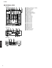
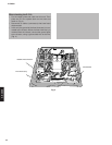
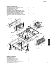
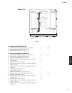
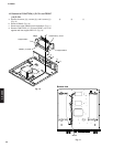
Fig. 5
9 0
A
B C
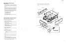
5. Removal of Amplifier Unit
a. Remove 8 screws (9) and 2 screws (0). (Fig. 5)
b. Remove the frame side L. (Fig. 5)
c. Remove 4 screws (A). (Fig. 5)
d. Remove CB71-74, CB76, CB84 and CB406. (Fig. 5)
e. Remove the amplifier unit L together with the heat sink.
f. Remove 4 screws (B) and 4 screws (C). (Fig. 5)
g. Remove CB52, CB54, CB64 and CB405. (Fig. 5)
h. Remove the amplifier unit R together with the heat
sink.
D
E
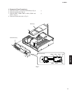
6. Removal of Power Unit
a. Remove 4 legs. (Fig. 5)
b. Remove 18 screws (D). (Fig. 5)
c. Remove the bottom cover. (Fig. 5)
d. Remove 4 screws (E). (Fig. 5)
e. Remove CB21-22, CB24-26 and CB34. (Fig. 5)
f. Remove the power unit. (Fig. 5)