


W102
CB52
CB72
CB54
CB75
CB55
IC102
W103
CB21
CB22
W303C
W104
CB24
W317
CB26
W303D
W303B
W303A
W316
W318
W315
W314
W304D
W304B
W304A
IC303
IC301
IC302
IC300
W304C
CB74
CB76
CB73
W204
W203
CB71
IC202
CB84
CB79 CB80
CB77 CB78
CB57 CB58
CB59
CB64
CB60
W202
A
1
2
3
4
5
6
7
8
9
10
BCDEFGH I JK
L MN
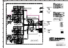
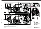
A-S2000
63
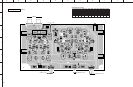
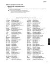
★ All voltages are measured with a 10MΩ/V DC electronic voltmeter.
★ Components having special characteristics are marked s and must be replaced
with parts having specifications equal to those originally installed.
★ Schematic diagram is subject to change without notice.
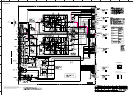
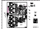
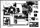
MAIN
AC89.5
AC48.5
DC51.4
DC51.4
AC38.5
AC38.5
AC38.5
AC38.5
DC51.4
DC51.4
58.258.2
58.2
58.2
2.9
2.9
3.4
-1.8
2.9
-2.0
60.2
-60.7
58.2
58.2
60.1
60.8
59.4
58.2
0.6
-50.9
0.6
-1.8
60.8
59.4
58.8
0.6
58.2
0.6
0
-50.9
50.9
-51.9
-51.4
-51.9
-52.4
-1.8
-51.2
-1.8
1.8
-52.4
-53.1
-1.8
-1.8
-53.1
-52.5
60.6
-53.3
-53.0
-0.8
-1.7
-0.7
-0.7-1.0
-1.0
-0.9
60.6
-1.7
-1.7
-1.7
-1.7
-1.7
-50.9
-53.2
60.8
-1.7
0
60.8
60.8
0
0.9
5.1
1.3
-0.7
12.7
-0.7
60.7
1.3
-0.5
50.8
50.3
-1.0
0.5
50.3
6.6
0
6.1
6.1
57.4
6.6
0
6.1
0.6 0.6
0
0
-1.0
-45.0
0.5
-45.5
-45.0
-1.0
-45.5
0
0
-22.1
-20.9
-1.0
-22.1
-39.8
-45.0
-57.3
0
1.1
0
22.0
39.8
21.2
1.1
22.2
0
0.6
61.1
-61.0
32.2
-32.2
24.6
0
4.6
-24.4
24.6
4.4
0
-23.8
-10.8
-15.5
-16.5
-15.6
4.8
4.6
33.6
33.6
-52.7
-53.8
5.1
34.1
-53.9
-52.8
5.1
0
-16.5
-15.6
-24.5
24.9
0
4.4
3.7
-16.5
-15.5
5.1
0
0
4.8
-16.5
-10.8
33.8
5.1
5.1
33.75.1
33.7
-52.7
-53.8
5.1
33.8
-53.9
-52.5
39.6
21.2
1.1
1.1
0
0.2
0
-0.1
-1.0
-0.5
-1.0
-45.5
-45.0
-45.0
0.5
-45.6
-45.0
6.1
50.4
6.1
6.6
0
6.0
6.6
57.4
60.8
12.6
-50.9
-51.6
-52.1
60.8
60.8
60.7
0
-1.5
-1.5
-1.5
-51.6
-52.5
-53.1
-1.5
-52.5
-53.1
-1.5
-52.5
-53.1
60.6
-53.1
-53.1
-1.2
-1.5
-1.2
-1.5
-1.2
60.6
-1.5
-53.1
-52.5
-1.5
-53.1
-52.5
-1.5
-53.1
-52.5
-1.5
60.8
58.8
58.8
59.5
60.2
59.8
60.2
58.3
58.3
0.6
0.6
0.6
0.6
58.8
-50.9
-56.7
-59.5
58.3
58.3
58.3
3.6
4.1
3.6
-1.4
-1.6
4.1
-1.4
58.3
58.3
3.6
4.1
-1.6
-1.4
3.6
0
-50.9
-55.7
-1.5
-52.6
-52.1
-1.5
-50.9
58.3
60.2
60.8
60.8
-60.7
-51.6
-1.5
-52.1
-51.6
-53.1
-53.1
-1.5
-53.1
-53.1
-1.5
-1.5
-52.5
-51.0
-0.6
-1.2
-0.6
-1.2
6.6
6.0
0.5
0
0
0.5
-57.2
-20.9
-21.8
-39.8
0
-21.8
-0.1
0.5
0
-0.5
-1.0
22.0
0.6
0
22.0
1.1
50.9
50.4
1.1
34.1
-15.5
-10.8
-15.5
-16.5
-16.5
-15.6
-10.8
-10.8
0
0
-16.5
-15.6
-10.8
-10.8
0
-16.5
-10.8
23.8
0.6
3.2
-23.8
3.7
6.6
0.5
6.1
1.1
0
-51.6
-52.2
-51.6
-52.2
-52.5
-53.1
-52.5
-52.6
-53.1
-53.1
-53.1
-53.5
-53.5
-53.3
-1.8
-52.4
-53.1
-1.8
60.8
60.8
59.8
3.4
3.4
-1.8
1.8
2.9
0
0.9
5.1
Ground point
Ground point
OUT L
IC102, 202: LM61CIZ
Temperature sensor
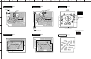
MAIN (1)
MAIN (2)
MAIN (3)
MAIN (4)
MAIN (5)
Idling adjustment
Idling adjustment
#
#
#
#
#
#
#
#
#
#
#
#
Head phone DC offset
Head phone DC offset
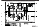
Note) Those parts marked with “#” are not included in the P.C.B. ass’y.
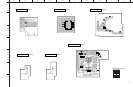
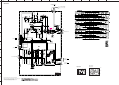
to FUNCTION (2)_CB406
Page 61
J3
to FUNCTION (2)_CB405
Page 61 J7
to FUNCTION (3)_CB25
Page 62
C6
to FRONT (11)_CB34
Page 66 B3
To POWER TRANSFORMER
To POWER TRANSFORMERTo POWER TRANSFORMER
To POWER TRANSFORMER
to MAIN (3)_W318
M2
to MAIN (2)_CB73
K8
to MAIN (2)_CB72
C9
to MAIN (1)_CB52
C5
to MAIN (2)_CB75
F6
to MAIN (1)_CB55
F1
to MAIN (3)_W314
M2
to MAIN (3)_W315
M2
to FRONT (2)_CB504
Page 64
C9
to FRONT (1)_CB521
Page 64
K8
to FRONT (12)_W101A, W101B
Page 66
H4
to FRONT (13)_W201A, W201B
Page 66
H8
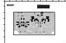
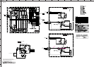
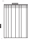
1. MAIN 3 P.C.B.
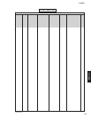
2. MAIN 3 P.C.B.
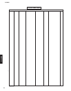
3. MAIN 3 P.C.B.
4. MAIN 3 P.C.B.
Safety measures
• Some internal parts in this product contain high voltages and are dangerous. Be sure to take safety measures during servicing, such as wearing insulating gloves.
• Note that positions indicated below are dangerous even after the power is turned off because an electric charge remains and a high voltage continues to exist there.
Before starting any repair work, perform discharge by connecting a discharge resistor (5k-ohms/10W) between terminals at following positions. The time required for
discharging is about 30 seconds.
1. C308 on MAIN (3) P.C.B..
2. C309 on MAIN (3) P.C.B..
3. C335 on MAIN (3) P.C.B..
4. C336 on MAIN (3) P.C.B..
5 k-ohms
10 W
5 k-ohms
10 W
5 k-ohms
10 W
5 k-ohms
10 W