


A-S2000
10
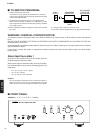
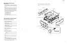
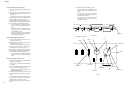
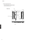
● When installing the knob VOL unit:
a. Turn the VOLUME (VR501) counterclockwise
fully. (Fig. 2)
b. Match the slit in the knob VOL unit with the
“VOLUME MIN” position and install it in that
state. (Fig. 2)
* At this time, do not tighten the lock set screw.
c. Keep about 0.5 mm to 0.75 mm clearance from
the front panel to knob VOL unit. (Fig. 2)
d. Match the lock set screw position with the cut in
VOLUME (VR501) and tighten the lock set screw.
e. After installation, perform following checks.
• Turn the knob VOL unit both directions to
check that it does not rub against the front
panel.
• Turn the knob VOL unit clockwise fully and
check that the slit in it matches with the
“VOLUME MAX” position.
• Turn the knob VOL unit counterclockwise
fully and check that the slit in it matches with
the “VOLUME MIN” position.
● When installing the knob SEL unit:
a. Turn the INPUT (SW501) so that the cut in it
comes at the top. (Fig. 2)
b. Install the knob SEL unit with its lock set screw
positioned at the top. (Fig. 2)
* At this time, do not tighten the lock set screw.
c. Keep about 0.5 mm to 0.75 mm clearance from
the front panel to knob SEL unit. (Fig. 2)
d. Match the lock set screw position with the cut in
INPUT (SW501) and tighten the lock set screw.
e. After installation, perform following checks.
• Turn the knob SEL unit in both directions to
check that it does not rub against the front
panel.
● When installing the knob TC unit
* Use the same installation procedure for BASS,
TREBLE and BALANCE.
Described here is installation of BALANCE as
an example.
a. Turn the BALANCE (VR504) in both directions
and set it to the center position. (Fig. 2)
* VR504 stops at the center position when it is
turned in both directions.
b. Match the slit in the knob TC unit with the center
position of BALANCE and install it in that state.
(Fig. 2)
* At this time, do not tighten the lock set screw.
c. Keep about 0.5 mm to 0.75 mm clearance from
the front panel to knob TC unit. (Fig. 2)
d. Tighten the lock set screw of the knob TC unit.
(Fig. 2)
Knob VOL unit
Slit
Cut
Lock set screw
Lock set screw
Lock set screw
Center position of BALANCE
VR501
SW501
VR504
VOLUME MIN
VOLUME MAX
Knob SEL unit
Knob TC unit
Front panel
0.5–0.75mm
Fig. 2
e. After installation, perform following checks.
• Turn the knob TC unit in both directions to
check that it does not rub against the front
panel.
• Turn the knob TC unit counterclockwise
fully and check that the slit in it matches with
the “BALANCE L” position.
• Turn the knob TC unit clockwise fully and
check that the slit in it matches with the
“BALANCE R” position.