


Model PA635 Page 5
© 2001 Xantech Corporation
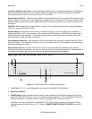
In STEREO mode, the two amplifiers operate independently of each other for 35 Watts of output each, except
IR control of Volume, Max-V, Mute, Standby OFF/ON and Balance functions is common to both.
In MONO mode, left and right input signals are summed internally for Mono output from each of the two
amplifiers. Also, either the Left or Right (item #5) input may be used if the source is already a Mono signal.
In BRIDGED mode, the two amplifiers are bridged for a single channel of high power output (150 Watts @ 8
Ohms). Either the Left or Right input (item #5) may be used to drive the resultant single channel amplifier.
CAUTION: Be sure to have the POWER turned OFF when changing the position of this switch and when
making the corresponding speaker connection changes (see also item #12, following).
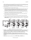
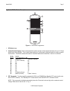
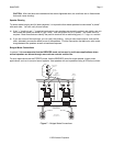
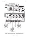
8. COMMON AUDIO BUS. A single audio source, such as from a connected preamp, can drive one or more of
the amplifier pairs simultaneously, as desired, from this Bus. Any of the amplifier pairs can be switched to the
COMMON AUDIO BUS at will by use of the COMMON BUS / LOCAL Switch (see also item #6).
9. LEVEL (System) RESET Button. Pressing this button 2 times within 1 second restores all factory default
settings. The factory defaults for all channels are as follows:
• Input Level set to 1 Volt rms for 3 Watts output.
• Balance centered.
• Mute OFF.
• MAX-V Cleared.
• IR Code Group set to B0 (the PA1235 uses code group A0).
• CI (control in) disabled. Changes CI control to IR control of Standby ON/OFF. (CI enables when +5 to
+30 VDC is applied to CI for 2 or more seconds. See also item #11).
NOTE: The PA635 will always return to last set values (plus any unaltered factory defaults) after main power
shut down or after any power interruptions.
10. FUSE. When required, replace only with a fuse of the same type and rating:
• 120 V Version: 6.25 AMP 250 VAC, SLOW BLOW.
• 240 V Version: 3.15 A Time-Lag 250 VAC.
• Replacement with a fuse of higher rating will not protect the amplifier and will void the warranty.
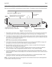
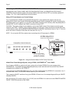
11. IR IN, STATUS, GROUND and CI Terminals. Removable, 4-Terminal, screw type plug-in connector.
• IR IN = IR Signal. Receives IR Input from Xantech IR Receivers, Smart Pads, Connecting Blocks, etc.
• STATUS Out. Delivers a constant +12 VDC output (9V @ 70 mA) with ON condition. 0 Volts output =
OFF (Standby).
• GROUND. Ground for IR IN, STATUS out & CI in.
• CI = Control Input. Use for control of Standby ON/OFF of amplifier pairs, if desired, instead of by IR. After
CI is enabled (see item #9), 0 Volts input = OFF (Standby) condition and +5 to +30 VDC input = ON
condition. (12V in draws 16 mA).
NOTE: All plug-in connectors accept wire sizes from 24 to 12 gauge.
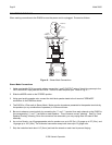
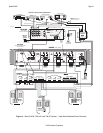
12. SPEAKER Terminals. These plug-in 4-terminal screw type connectors permit speaker wire sizes up to 12
gauge. When making connections for the STEREO mode, be sure to observe the "+” and "–" polarity
markings, just under the LEFT & RIGHT markings, for each wire pair going to the speakers.
CAUTION: When making connections for the BRIDGED mode, remember, only one speaker is being
attached per amplifier pair. Be sure to observe the outer "+” and "–" polarity markings on each side of the