


Model PA635 Page 17
© 2001 Xantech Corporation
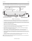
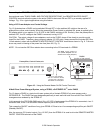
CAUTION: When making this connection, do not use the included 220 Ohm resistor! Refer also to CAUTION
notes, Fig. 9.
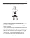
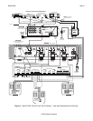
When any one of the zones is turned ON, the common CO goes high (+12V), turning on power to the entire
PA635. Similarly, when the last zone is turned OFF, the CO drops to 0 V, turning the PA635 totally OFF.
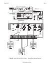
NOTE: No IR control of the PA635 is used in the system shown in Fig. 11. All volume, mute, etc. functions are
handled by IR control of the ZPR68-10. The PA635 amplifier pairs are all set to the default volume level setting
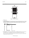
by pressing the LEVEL (System) RESET button (refer to item #9, Fig. 3).
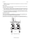
AC Power Management of the entire system as shown in Fig. 11 is accomplished, therefore, as follows:
a) The PA635 is controlled via the STATUS and CO functions as noted above.
The Source Components are controlled via the GATEKEEP-IR
™
sensor system and the IR macros in the Smart
Pads and, where used, IR macros in Learning Remotes (such as the Xantech URC types).
CAUTION: When powering up multiple PA635’s, a delay of 2 or more seconds should be incorporated between
“power on” using multiple Xantech AC2’s.