


Page 10 Model PA635
© 2001 Xantech Corporation.
CONNECTING THE PA635
When making connections to the PA635 be sure the power cord is unplugged. Proceed as follows:
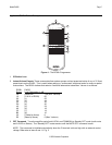
COMMON
LOCAL
CI
GROUND
STATUS
IR IN
STEREO
MONO
BRIDGED
MODE
LEFT RIGHT
SPEAKER
+-- --+
+ BRIDGED --
LEFT RIGHT
1
VIDEO
AUDIO
L
R
1
RCA Type
Patch Cords
Preamp Outputs
ZPR68, etc.
PA635
Rear Panel
+
Be sure speakers are
connected with correct
polarity as shown.
Wall speakers,
shelf speakers, etc.
Left Right
Set MODE
Switch to
STEREO position
+
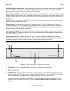
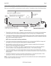
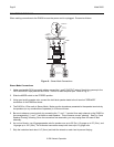
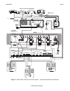
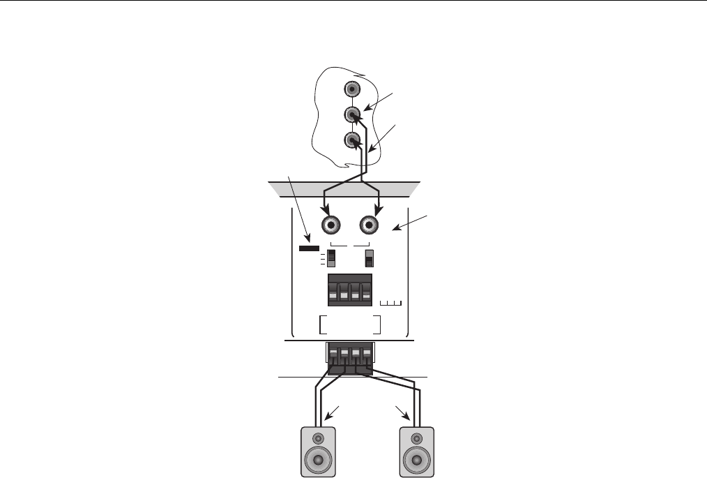
Figure 6 – Stereo Mode Connections
Stereo Mode Connections
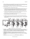
1. Using good quality RCA-type patch cables, connect the L and R OUTPUT jacks of the driving preamp to the
LEFT and RIGHT input jacks on the PA635. Do this for each amplifier pair. Refer to Fig. 6.
2. Slide the MODE switch to the STEREO position.
3. Using good quality speaker wire, connect the individual speaker leads to the 4-terminal "SPEAKER"
connectors on the PA635 as shown.
4. The PA635 is 4-Ohm safe in Stereo Mode. Make sure the impedance presented to the speaker terminals by
the speakers (or any combination of speakers) is 4-Ohms minimum.
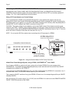
5. Be sure to observe correct polarity by connecting the "+" and "–" terminal from each channel on the PA635 to
the corresponding "+" and "–" terminals on each speaker. This will ensure correct "phasing". See Fig. 6 and
Speaker Phasing, following. Since the connectors are removable, you may unplug them for ease of lead
assembly.
6. As a rule of thumb, use 18 gauge speaker wire for speaker runs up to 30' (9m), 16 gauge up to 70' (21m), and
14 gauge up to 150' (39m). The 4-terminal connectors accept wire sizes up to 12 gauge max.
7. Strip the insulation back about 1/4" (6mm) and twist the strands on each lead to prevent fraying.