


Page 4 Model PA635
© 2001 Xantech Corporation.
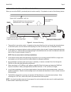
NOTE: The PA635 may also be powered ON/OFF with an external AC line switch into which the power cord
of the PA635 is plugged (such as the switched AC outlet of a preamp, timer, etc. with a 10A rating). For this
type of operation, leave the POWER switch depressed to the MANUAL ON position.
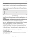
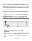
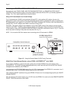
4. Status LED Indicators. These indicators, one for each channel pair, provide the following status information:
a) They show Power ON/OFF and Standby ON/OFF conditions.
b) They flash Amber 5 times during power up, then turn steady Green when Power On Mute releases. This
action occurs whether the unit is powered ON and OFF by the POWER switch (item # 3) or by a DC
voltage applied to the REMOTE MASTER ON/OFF CONTROL terminals (item #13). Be sure the rear
panel master AC LINE ON/OFF Switch, item #17, is set to the ON (I) position for the above to occur.
c) They will go off when the Standby OFF IR command is received. Sending a MUTE OFF command will
restore operation. Also, each LED blinks with Volume action for that channel.
d) A Mute command will cause the channel LED to blink Green (Red if Volume is within 5 dB of Max-V).
Mute is released when any other PA635 command is sent.
e) Changing an IR Code Group will cause them to blink Amber, confirming the change has taken effect.
f) When the volume level is increased to a range within 5 dB of MAX-V, the LED color changes from Green
to Red. NOTE: Red indicates that volume gain setting is approaching maximum --- not an indication of
power output level.
WARNING
TURN POWER
OFF BEFORE
CHANGING
MODES
CAUTION
RISK OF ELECTRIC
SHOCK. DO NOT OPEN
REMOTE
MASTER
ON/OFF
CONTROL
5-30 VOLTS DC
LEFT RIGHT
COMMON
AUDIO
BUS
+--
CI
GROUND
STATUS
IR IN
COMMON
LOCAL
CI
GROUND
STATUS
IR IN
STEREO
MONO
BRIDGED
MODE
LEFT RIGHT
SPEAKER
+-- --+
+ BRIDGED --
COMMON
LOCAL
CI
GROUND
STATUS
IR IN
STEREO
MONO
BRIDGED
MODE
LEFT RIGHT
SPEAKER
+-- --+
+ BRIDGED --
COMMON
LOCAL
CI
GROUND
STATUS
IR IN
STEREO
MONO
BRIDGED
MODE
LEFT RIGHT
SPEAKER
+-- --+
+ BRIDGED --
WARNING
TURN POWER
OFF BEFORE
CHANGING
MODES
FUSE
6.25 AMP
SLOW BLOW
AC 120V
60 HZ
2 AMP
®
AC LINE
ON/OFF
LEFT RIGHT
2
LEFT RIGHT
1
LEFT RIGHT
3
LEVEL
RESET
8
9
7
5
6 7
5
6 7
5
6
10
18
17
12
11
12
11
12
11
1514
16
13
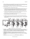
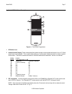
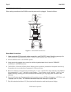
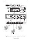
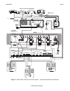
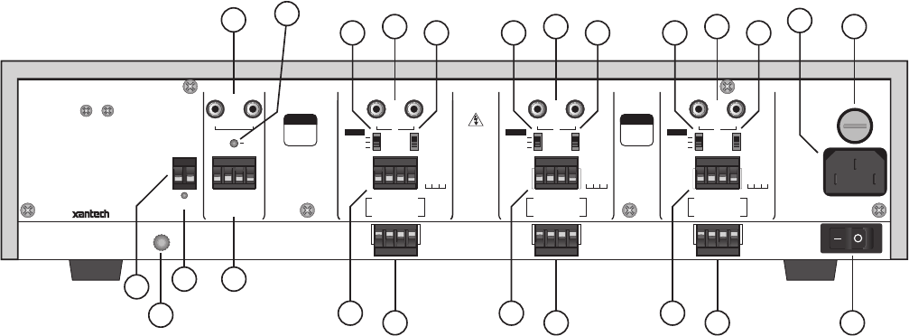
Figure 3 – PA635 Rear Panel – Features and Functions
5. Line Inputs. These RCA-type jacks are the audio inputs for each of the amplifier pairs. Connect them to the
OUTPUT jacks of the driving preamp with good quality RCA-type patch cables. Note that the inputs are
marked LEFT-1-RIGHT, LEFT-2-RIGHT, etc., signifying the stereo channel pairs. Both the LEFT and RIGHT
jacks are also active when the MODE switch (item #7) is set to the MONO or BRIDGED mode.
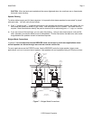
6. COMMON BUS / LOCAL Switch. Switches the amplifier stereo pair inputs between the LOCAL
(LEFT/RIGHT) jacks, item #5 and the COMMON AUDIO BUS (LEFT/RIGHT) jacks, item #8. In this way,
each amplifier pair can be driven by separate zones or sources or from a common source via the COMMON
AUDIO BUS.
7. MODE Switch. Switches the amplifier pair between STEREO, MONO and BRIDGED modes.