


Page 16 Model PA635
© 2001 Xantech Corporation.
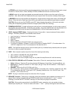
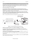
Connecting the REMOTE MASTER ON/OFF CONTROL Terminals
As mentioned under "PA635 PANEL AND FEATURE DESCRIPTIONS", the REMOTE MASTER ON/OFF
CONTROL terminals allow the power to the entire PA635 to be turned ON and OFF by a remotely applied DC
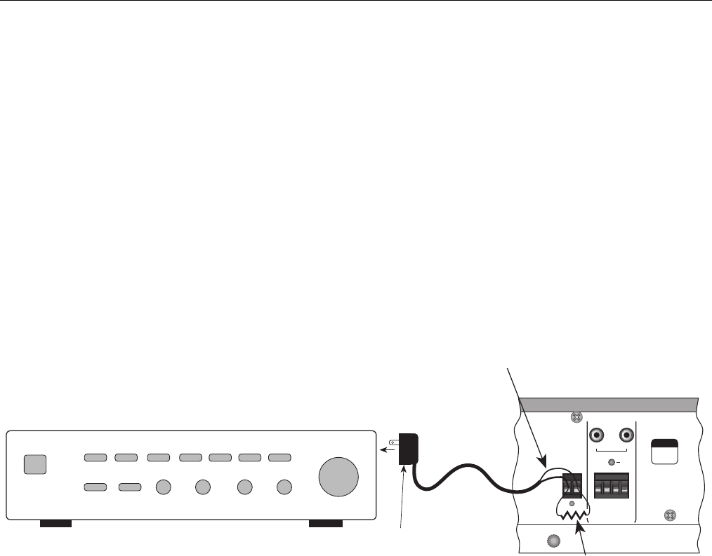
Voltage. Fig. 10 is a typical applications using this feature.
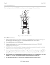
Using a DC Power Adapter as a Control Voltage
Fig. 10 illustrates how a PA635 can be switched ON and OFF via the switched AC outlet on the rear of a
preamplifier or other control center. When the preamplifier Power Switch is switched ON, power is applied to the
DC adapter which in turn applies 5 V to 30 VDC to the PA635, switching it ON. Similarly, when the preamplifier is
switched OFF, the DC voltage to the PA635 is removed, turning it OFF.
CAUTION: The output voltage of some adapters, such as the 781RG, drops off too slowly to provide a quick
turnoff for the PA635. Therefore, when using any adapter (12 VDC max), always connect the included 220 Ohm
1 Watt resistor in shunt with the REMOTE MASTER ON/OFF CONTROL terminals as shown in Fig. 9. Failure to
do so may result in blowing of the power line fuse (item #10, Fig. 3).
NOTE: Do not use the 220 Ohm resistor when connecting to the CO terminals of a ZPR68!
REMOTE
MASTER
ON/OFF
CONTROL
5-30 VOLTS DC
LEFT RIGHT
COMMON
AUDIO
BUS
+--
CI
GROUND
STATUS
IR IN
WARNING
TURN POWER
OFF BEFORE
CHANGING
MODES
®
LEVEL
RESET
5V to 12 VDC Adapter,
such as a Xantech 781RG,
plugged into a Switched
AC Outlet on Preamplifier
Preamplifier, Control Center, etc.
This must be the positive (+)
lead (white striped lead on
Xantech Power Supply Adapters)
PA635
(portion of rear panel)
(+)
CAUTION:
You must use the included
220 ohm resistor.
Figure 10 – Using the Remote Master On/Off Control Terminals
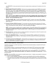
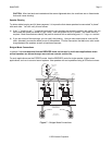
A Multi-Zone Power Managed System, using a ZPR68, a GATEKEEP-IR
™
and a PA635
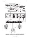
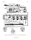
Fig. 10 shows a PA635 in a typical multi-room system with a Xantech ZPR68-10 six-zone preamp and a
GATEKEEP-IR. The PA635 has been designed specifically to work well with both Zone and All-Zone ON/OFF
management as rendered by the ZPR68-10.
In this example, the STATUS & GND output (0 to +12 VDC) of each zone of the ZPR68-10 is connected, via a 2-
conductor lead, to the CI & GROUND of each amplifier pair on the PA635.
This causes the ON/OFF condition of any given ZPR68-10 Zone to turn it's corresponding amplifier pair ON/OFF
(Standby ON/OFF).
Also, the common CO (control output, 0 to +12 VDC) from the ZPR68-10 is used to drive the REMOTE MASTER
ON/OFF CONTROL terminals of the PA635.