Model PA635 Page 3
© 2001 Xantech Corporation
Individual ON/OFF of Amp Pairs. Permits Standby ON/OFF control of individual channel pairs. Specifically, it
permits the STATUS outputs (12 Volts On/Off) of Xantech ZPR68 zones to switch the Standby of the PA635
channel pairs (CI) On and OFF with zone ON and OFF commands.
Remote Master ON/OFF. Allows the entire PA635 to be powered ON and OFF by a positive DC voltage ranging
between 5 and 30 volts (16mA @ 12V). Specifically, it permits the 12 Volt common CO (Control Output) on the
Xantech ZPR68 to power one or more PA635's ON and OFF automatically with first zone ON and last zone OFF
commands.
CAUTION: When powering up multiple PA635’s, a delay of 2 or more seconds should be incorporated between
“power on” using multiple Xantech AC2’s.
Default settings. As received from the factory, Volume level is set to 1 Volt for 3 Watts output, Balance is
centered and Mute is OFF, for all channels. Also, pressing the LEVEL (System) RESET switch 2 times within 1
second restores all factory defaults. The PA635 will always return to last set values (volume, etc.) after main
power shut down or after any power interruptions.
Low Impedance Capability. Each amplifier is 4-Ohm safe under music conditions in stereo mode and 8-Ohm
safe when bridged. This means, for instance, that you can drive two pairs of 8-Ohm speakers in stereo mode in
each zone with ease and safety.
Auto Protection Circuit. Protects the PA635 if a short or very low impedance is detected at the speaker
terminals or excessive temperatures are reached. Each amplifier pair is protected separately. Normal operation
is restored automatically when the short is removed or when temperatures drop sufficiently.
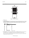
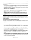
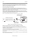
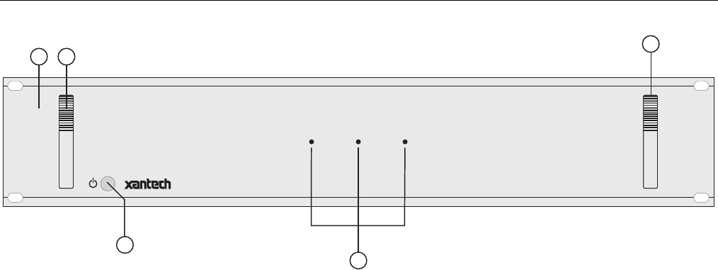
PA635 PANEL AND FEATURE DESCRIPTIONS (refer to Figure 2)
1
2
3
POWER
PA635 SIX CHANNEL AMPLIFIER
1
2
3
2
3
1
2
4
Figure 2 – PA635 Front Panel – Features and Functions
1. Front Panel. 19" x 3 ½" panel designed for mounting into a standard 19" Rack Panel.
2. Rack Panel Handles.
3. POWER Switch. When pressed to the IN position, power is applied to the PA635 [provided the rear panel
master AC LINE ON/OFF Switch, item 17, is placed in the ON (I) position]. This is the MANUAL ON position.
When pressed again, it releases to the OUT position (MANUAL OFF), turning the unit OFF.
In addition, this switch must be left in the MANUAL OFF (OUT) position to permit an external DC Control
Voltage to power the PA635 ON and OFF. Refer to "REMOTE MASTER ON/OFF CONTROL" terminals,
item #13.


