


Page 12 Model PA635
© 2001 Xantech Corporation.
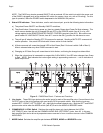
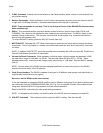
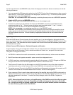
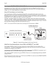
To make connections for the BRIDGED mode, follow the steps given before for stereo connections, but with the
following differences:
1. You may connect the RCA-type patch cables from the OUTPUT jacks of the driving preamp or other source to
either the LEFT or the RIGHT input jacks of the bridged pair, as shown in Fig. 7. Do this for just the amplifier
pairs you wish to run in the bridged mode.
CAUTION: Be sure Power is OFF when connecting or switching the amp into or out of BRIDGED operation.
2. Slide the MODE switch to the BRIDGED position.
NOTE: Do this only on the amplifier pairs you wish to run in the bridged mode!
3. Connect one speaker wire pair between the 4-terminal "SPEAKER" connectors on the PA635 and the
speakers as shown in Fig. 7. Be sure to use only the two outer terminals marked "+” and "–" on the 4-
terminal connector as shown on the panel for BRIDGED connections.
NOTE: Only one speaker is connected per amplifier pair in the BRIDGED mode!
CAUTION: When operating in the BRIDGED mode (particularly when bench testing the amplifier) do not
make a ground or any other kind of connection to the amplifier speaker terminals other than those to the
individual speakers as shown. Failures caused by inappropriate connections are not covered under the
warranty.
Typical Applications
Since the PA635 has an IR control system for each amplifier pair, it can be configured so that each individual
room, in a multi-room system, can have Line Level Volume, Mute, Balance, and Standby ON/OFF action via IR or
Smart Pad control. This eliminates the need for speaker level volume controls and their attendant power losses
and reduced sound quality.
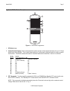
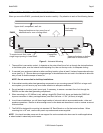
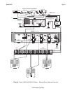
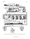
A Basic Common IR Bus System - Dedicated Keypads and Remotes.
A typical system using a low cost approach is shown in Fig. 8. It does require that a dedicated remote be used in
each room that has an IR receiver - that is, remote commands for Volume, etc., are specific for each room.
The system is configured as follows:
1. An RS41AV is used as a low cost 4-source selector, an ideal solution when only a few sources are desired.
2. Both IR receivers and keypads are used for system control from designated rooms.
3. A CB18 is used as a convenient parallel connecting block for the common +12 VDC, IR signal and GND bus
wiring for all the home runs from the keypads and IR receivers in the remote rooms.
4. The Common IR is taken from the #2 connector on the CB18 (connection to any of the other connectors
would also work) and run to the Common IR IN on the PA635 with a 2-conductor lead. Refer to Fig. 8.
5. To provide common IR control to the RS41AV and the Source Components and to power the keypads and IR
receivers, three leads are connected between the CB18 and a 789-44 Connecting Block.
6. Since a common IR bus is used to keep costs low, each of the amplifier pairs on the PA635 must be set to a
different IR Code Group number, so that Volume, Mute, Balance and Standby ON/OFF in each room can be
adjusted independent of the others. To make Code Group changes, refer to the RC68+ Programmer
Instructions.
NOTE: When shipped from the factory, all amplifier pairs of the PA635 are set to Code Group number
B0. You may, for example, leave the #1 amplifier pair at B0 and change the other two to C0 and D0,
etc. Just be sure not to use a group number that is used by any other Xantech product connected on
the same IR bus (e.g. #20 used on the RS41AV).