Wolf Cinema Owner's Manual
D-1
APPENDIX D
SYSTEM INTEGRATION
The GPIO (General Purpose Input Output) connector located on the input panel provides a
exiblemethodofinterfacingawiderangeofexternalI/Odevicestotheprojector.Thereare
sevenGIOpinsavailableonthenine-pinD-SubGPIOconnector,whicharecongurablevia
RS232 commands. The other two pins are reserved for ground and power – see table below for
pinidentication.
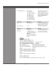
GPIO Pins GPIO
Pin # Signal
1 + 12V (1200mA)
2 GPIO 1
3 GPIO 2
4 GPIO 3
5 Ground
6 GPIO 4
7 GPIO 5
8 GPIO 6
9 GPIO 7
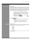
Conguring the GPIO
TheGPIOconnectorcanbeconguredtoautomateanynumberofeventsusingtheserial
commandcode GIO.Eachpin isdened aseither aninputoroutputdepending onthe
desired outcome. Ingeneral, congure thepin as aninput if youwant the projectorto
respond to something the external device does and as an output if you want the external
devicetorespondtoanactiontakenbytheprojector.Forexample,congurethepinasan
output if you want the lighting in a room to automatically dim when the projector is turned
on.
By using the GIO command, you can also set the state of each pin as high or low. By default,
the state of each pin is high. The voltage applied to pins in the high state is + 3.3V.
Example 1. Turn room lighting on when the projector is turned off. (Assumes a control/
automation unit is congured to turn the lights on when pin 2 of its input goes high.)
(GIO C2 O) Set pin #2 conguration to output
(GIO 2 H) Set pin #2 to high (state)
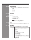
Query Command
(GIO?) Request the state and conguration of all pins
(GIO! “HHLLHLH” “OOIOOOI”) Reply of pin state and conguration
(GIO? C2) Request conguration for pin #2
(GIO! C2 O) Reply with pin #2 conguration as output
(GIO? 2) Request the state of pin #2
(GIO! H) Reply with pin #2 state as high
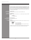
The serial cable required for connecting
the external device to the projector’s GPIO
connector, whether it’s a standard serial cable
or a custom one, must be compatible with the
external device.


